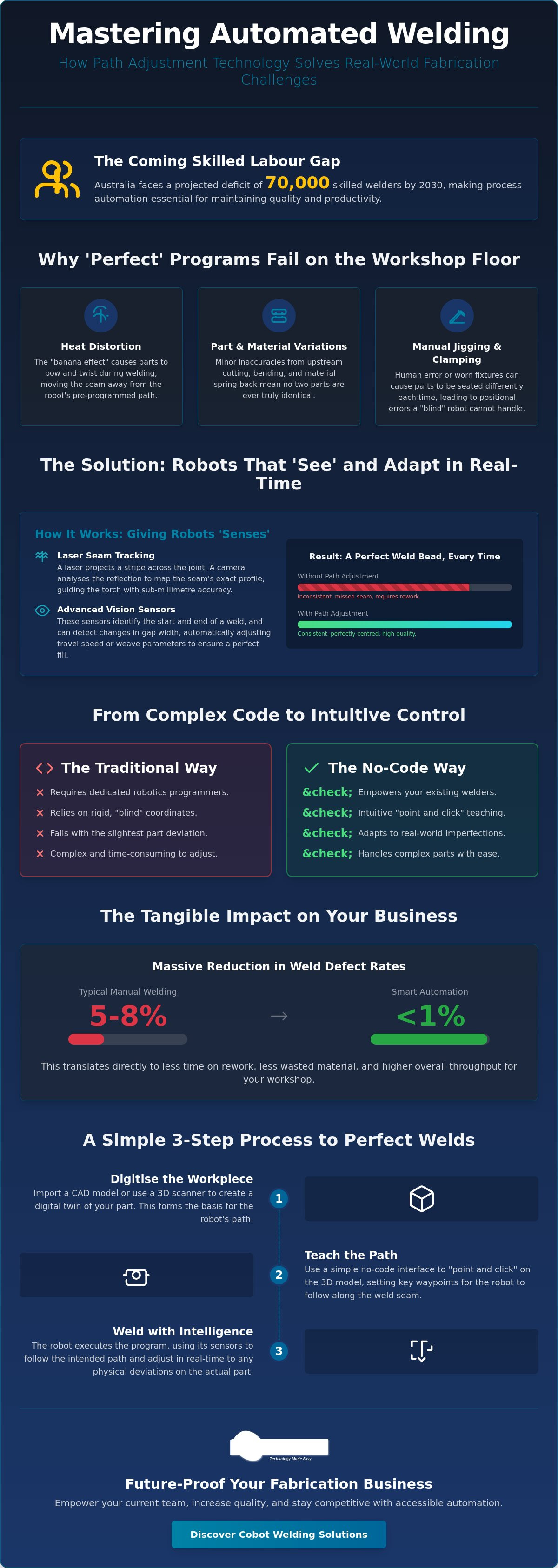
What if the secret to a perfect weld bead wasn't finding a rare robotics expert, but simply giving your current team the right tools to teach the machine? Many workshop managers are currently facing a projected deficit of 70,000 skilled welders in Australia by 2030, making it harder than ever to maintain quality. You've likely seen how heat distortion or inconsistent gaps can turn a standard job into a rework nightmare. Implementing automated welding path adjustment is the practical way to solve these issues, ensuring your robot follows the seam accurately even when the parts aren't perfect.
We know that the leap to automation can feel intimidating, especially if you're worried about complex coding. This article outlines the practical steps to master path adjustment using no-code teaching software and collaborative robot cells. You'll learn how to empower your existing welders to use these tools, reducing manual grinding and achieving consistent results on every part. We'll walk through how to organise your setup and support your team, helping you turn your workshop into a more efficient, high-quality production line.
Key Takeaways
- Understand how automated welding path adjustment enables robots to "see" and correct for part deviations, significantly reducing rework caused by heat distortion.
- Discover the role of laser seam tracking and vision sensors in identifying joint orientation and gap widths in real-time on the workshop floor.
- Compare traditional programming hurdles with modern no-code interfaces that allow your team to "point and click" rather than write complex code.
- Master a simple step-by-step process for digitising workpieces and setting visual waypoints using 3D scans or CAD models.
- Learn how to future-proof your business by choosing accessible automation that empowers your current staff and handles increasing part complexity.
Why Part Deviations and Heat Distortion Require Automated Welding Path Adjustment
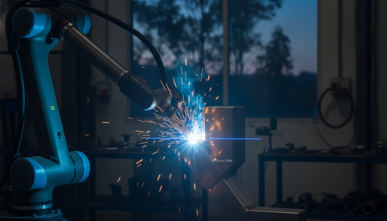
In many Australian fabrication shops, the dream of automation often hits a practical wall when the second or third part comes off the line. You've programmed the robot perfectly for the prototype, but real-world parts are rarely identical. This is where automated welding path adjustment becomes essential. Rather than following a rigid, "blind" set of coordinates, this technology gives the robot the ability to "see" the joint and correct its trajectory in real time. It transforms the robot from a simple machine into an adaptive tool that understands the reality of the metal in front of it.
Traditional "fixed" automation relies on the assumption that every part, jig, and clamp is 100% precise. On a busy workshop floor, we know that isn't the case. If a part is slightly out of alignment or a jig has a millimetre of play, a fixed program will miss the seam entirely. The Technology Behind Real-Time Path Correction allows the system to identify these small deviations and shift the weld path to compensate, ensuring the bead lands exactly where it should.
Heat distortion, often called the "banana effect," is another major hurdle for fixed programs. As you apply heat to a long weldment, the metal naturally expands and pulls, causing the part to bow or twist during the process. A robot running a pre-set path cannot account for a part that is literally changing shape as it works. By implementing automated welding path adjustment, the system tracks the seam as it moves, maintaining the correct torch angle and contact-to-work distance despite the thermal movement of the material.
The Hidden Costs of Inconsistent Weld Paths
When an automated system lacks the ability to adjust, the "efficiency" of the robot is quickly cancelled out by the time spent on manual grinding and rework. Industry data suggests that manual operations often see defect rates between 5% and 8%, while smart automation can pull that figure below 1%. Every missed seam or inconsistent gap leads to burn-through or a lack of penetration, which forces your most skilled welders to spend their day "fixing" the robot's mistakes. This doesn't just hurt your bottom line; it disrupts your production schedule and can damage the trust your clients place in your workshop's consistency.
Common Sources of Positional Error
Even the best-run shops face positional errors from sources that are often beyond the welder's control. These include:
- Upstream Inaccuracies: Slight variations in plasma or laser cutting tolerances can create cumulative errors in the final assembly.
- Manual Jigging: Human error during clamping or the use of worn fixtures can lead to parts being seated differently every time.
- Material Variations: Different batches of local steel can exhibit varying levels of spring-back after bending, meaning the part geometry isn't always what the CAD model predicts.
By acknowledging these realities, you can move away from trying to force "perfect" parts and instead use automation that is smart enough to handle the imperfections of the trade.
The Technology Behind Real-Time Path Correction and Seam Tracking
To understand how automated welding path adjustment works, we need to look at the hardware and software that give the machine its "senses". Laser Weld Seam Tracking (LWST) is one of the most reliable methods used on the workshop floor today. It works by projecting a laser stripe across the joint just ahead of the welding torch. A camera then captures the reflection, using triangulation to calculate the exact profile of the seam. This allows the system to shift the robot's arm in real time, keeping the torch centred even if the part is slightly misaligned or warped.
Vision sensors do more than just find the start of a weld. They are capable of detecting variations in gap width and joint orientation as the robot progresses. If the gap between two plates opens up due to poor fit-up, the software can automatically adjust the travel speed or weave width to compensate. Dealing with Welding Automation Challenges like these requires a system that doesn't just follow a line but reacts to the environment it sees.
For heavier fabrication involving thicker plates, Through-Arc Seam Tracking (TAST) is often the preferred choice. TAST doesn't use a separate camera; instead, it monitors the electrical characteristics of the arc itself. As the robot weaves the torch across the joint, the system detects changes in current or voltage. If the torch moves too far from the sidewall, the electrical feedback tells the software to correct the path instantly. This method is incredibly robust because it isn't affected by the bright light or smoke of the welding process.
Sensors vs. Software: Who Does the Heavy Lifting?
It is helpful to think of the sensors as the "eyes" and the software as the "brain". While high-quality sensors collect the raw data, it's the software that translates those signals into movement. In the past, calibrating these systems required a specialist programmer. Modern no-code teaching software has changed this by providing a visual interface that your existing staff can use. If you want to see how this looks in a real-world setup, our collaborative robot welding cells are designed to make these complex adjustments accessible to any experienced welder.
Adaptive vs. Fixed Automation
Fixed automation is only suitable for high-volume production where every part is identical. However, most Australian fabrication shops operate in a high-mix, low-volume (HMLV) environment. You might be welding a different assembly every day. Adaptive paths provide the flexibility to handle these changing jobs without needing a "perfect" setup every time. This approach allows you to scale your automation as your part complexity increases, ensuring your investment remains useful as your business grows.
Comparing Traditional Programming with Modern No-Code Path Adjustments
For decades, the biggest hurdle for small Australian manufacturers wasn't the cost of the robot arm itself, but the complexity of telling it what to do. Traditional robot programming relies on the "Teach Pendant," a handheld terminal used to manually jog the robot to hundreds of individual points. This process is tedious and requires a specialised skill set that is increasingly hard to find. When you need to implement automated welding path adjustment, doing so through traditional coding can take weeks of fine-tuning before a single production part is joined. For a job shop handling small batches, this downtime simply isn't viable.
Modern no-code interfaces have flipped this model on its head. Instead of writing lines of G-code or jogging a joystick for hours, operators can now use intuitive "point and click" software to set their paths. This shift has lowered the barrier to entry for local fabricators, allowing them to compete with larger offshore operations. By removing the need for a dedicated "Robot Programmer," the responsibility shifts back to the person who knows the craft best: the welding operator. This transition ensures that the technical nuances of a good weld are maintained without the operator needing a degree in computer science.
Time-to-Production: A Real-World Comparison
In a traditional setup, the time spent programming a new part often exceeds the actual welding time, especially for complex geometries. If you're welding a batch of ten custom frames, spending two days on a "Teach Pendant" destroys your margin. No-code adjustments allow you to import a CAD file or use a 3D scan to generate a path in minutes. The setup-to-weld ratio is the key metric for small batch profitability. By keeping this ratio low, you ensure that automated welding path adjustment adds value to every job, rather than just the high-volume ones.
Empowering Your Existing Workforce
Your best welders already understand how metal reacts to heat and how a bead should look. They make the best cobot operators because they have the "trade memory" that a programmer lacks. Intuitive visual interfaces remove the fear of "breaking the code," encouraging your team to experiment and refine their setups. Using no-code robot welding software keeps your intellectual property on the workshop floor where it belongs. It treats the robot as a sophisticated tool in the welder's hand, rather than a replacement for their expertise. This supportive approach builds confidence across your team, making the transition to automation a collaborative success rather than a source of stress.

How to Adjust Weld Paths Using No-Code Software: A Step-by-Step Guide
Moving from a manual process to an automated one doesn't have to be a headache. Once you've got your hardware in place, the software becomes your primary tool for refining the process. Mastering automated welding path adjustment is a logical progression that starts with a digital model and ends with a perfect bead. Here is how you can manage that workflow on your own workshop floor.
- Step 1: Digitising the Workpiece. Start by importing your CAD model or using a 3D scan to create a virtual replica of the part. This gives the software a baseline to work from.
- Step 2: Identifying the Seam. Use the visual interface to click on the start and end points of your weld. You're essentially setting waypoints that the robot will follow, much like drawing a line on a digital map.
- Step 3: Adjusting Parameters. Set your welding variables such as travel speed and voltage. You can also adjust the angle of attack and standoff distances using simple sliders, completely bypassing the need to write code.
- Step 4: Running a Simulation. Before you strike an arc, run a dry-run simulation. This allows you to check for potential collisions with jigs or the part itself, ensuring the robot's reach is clear.
- Step 5: Live Deployment. Send the program to the robot and monitor the first "live" bead. The system uses automated welding path adjustment to account for any minor differences between the digital model and the physical part in the jig.
Fine-Tuning the Torch Geometry
A common mistake in basic automation is ignoring the torch's relationship to the joint. With no-code software, you can easily adjust the "work angle" and "travel angle" within a 3D visualiser. This is critical for ensuring consistent penetration, especially on curved surfaces where the torch needs to pivot to stay perpendicular. Depending on your material thickness, you might choose to "lead" the arc for better control or "trail" it for deeper penetration. The software ensures that your tool standoff remains constant, even if the part geometry is complex.
Handling Deviations on the Fly
No matter how good your jigs are, parts will eventually shift. You can configure "search" routines that tell the robot to touch the part or use a sensor to find the exact location before it starts welding. This allows the software to adjust for rotational changes in the jig or slight variations in how the part was clamped. By verifying the adjusted path through the software’s digital twin, you can be confident that the robot has correctly "found" the seam. If you're ready to see this in action, you can book a mobile demo system to test these features on your own parts.
It's important to remember that the software is designed to support your expertise, not replace it. By using these visual tools, you're giving your team the ability to solve production problems quickly without waiting for an external programmer to arrive.
Future-Proofing Your Fabrication with Accessible Automation
For many Australian fabrication shops, the "wait and see" approach to new technology often feels like the safest bet. However, with a projected deficit of 70,000 skilled welders by 2030, the cost of sticking with purely manual processes is rising every day. Relying on manual grinding and rework to fix part deviations isn't just a waste of time; it's an unnecessary drain on your workshop's profitability. By adopting automated welding path adjustment now, you aren't just buying a machine. You are building a more resilient business that can handle the reality of modern manufacturing without needing to find rare, specialised programmers.
Selecting a system that grows with your business is vital. You might start with simple assemblies today, but your customers' needs will inevitably become more complex. A flexible system allows you to integrate advanced features like real-time seam tracking as you need them. This scalability ensures that your investment remains a valuable asset on your floor for years to come. Positioning your workshop as a high-tech leader in the local market also helps you attract the next generation of tradespeople who want to work with modern, supportive tools rather than outdated equipment.
Starting Small with Collaborative Cells
If you're new to automation, a collaborative robot welding cell is often the most practical entry point. Unlike traditional industrial robots that require extensive safety guarding and permanent floor space, cobots are designed to work alongside your team. Their mobility is a significant advantage for high-mix environments where you might need to move the cell between different workstations throughout the week. Integrating automated welding path adjustment into these cells means your existing quality control workflow becomes much more predictable, as the robot handles the repetitive corrections that usually lead to human fatigue.
The TME Systems Approach: Partnership Over Transaction
We believe that successful automation is built on a relationship, not just a sale. Our focus is on providing the no-code tools and the operator training and onboarding necessary to make your transition seamless. We understand that seeing is believing, which is why we offer a mobile demo system that brings the technology directly to your door. This allows you to see exactly how path adjustment handles your specific parts and your unique shop conditions before you make a commitment.
At the end of the day, automation is a tool for the welder, not a replacement for the craft. A robot can follow a path with incredible precision, but it still needs the trade knowledge of an experienced professional to set the right parameters. By combining traditional craftsmanship with accessible technology, you can ensure your workshop stays competitive, efficient, and ready for whatever the future of Australian manufacturing holds.
Taking the Next Step Toward Smarter Fabrication
Empowering your workshop with automated welding path adjustment is a practical way to overcome the daily frustrations of part deviations and heat distortion. By choosing no-code tools, you keep your trade expertise where it belongs; with your experienced welders. This shift doesn't just reduce rework; it builds a more resilient production line that can handle high-mix, low-volume jobs with ease. You've seen how the technology works and how simple the workflow can be. Now it's time to see it on your own floor.
We are an Australian-owned and operated team specialising in no-code integration for local fabricators. Our turnkey cells are designed for the specific demands of the Australian workshop floor, providing you with a reliable partner for long-term success. If you want to see these results firsthand, book a mobile welding robot demonstration to see no-code path adjustment in action. We'll bring the system to your site so you can test it on your actual parts. Let's work together to make your workshop more efficient and your team more capable than ever before.
Frequently Asked Questions
What is automated welding path adjustment?
It's the robot's ability to identify the real-world position of a joint and shift its programmed trajectory to match. This ensures the arc stays centred on the seam even if the part has moved, distorted, or wasn't clamped perfectly. It moves the system away from rigid, pre-set coordinates toward a reactive process that handles the common imperfections found in manual fabrication.
Do I need to know how to code to adjust robot weld paths?
No, you don't need any programming experience. Modern systems use no-code teaching software that replaces complex lines of script with an intuitive visual interface. Your experienced welders can adjust the path by clicking on a 3D model or using a touch-screen to set waypoints. This removes the need for a specialised programmer and puts control back into the hands of your trade experts.
Can a welding robot handle parts that aren’t perfectly identical?
Yes, this is exactly what automated welding path adjustment is designed to solve. By using sensors like laser seam trackers or through-arc feedback, the robot detects millimetre-level deviations in each part. It then corrects its path on the fly, ensuring that even if your upstream cutting or jigging varies slightly, the weld quality remains consistent across the entire batch.
How much time does it take to set up a new weld path with no-code software?
You can typically go from a CAD file to a ready-to-weld program in minutes rather than hours or days. Because you aren't manually jogging a teach pendant to every single point, the setup time is slashed. This rapid turnaround makes it profitable to use automation even for very small batches or one-off custom jobs that were previously too expensive to automate.
What happens if the robot hits a clamp during path adjustment?
Most collaborative systems include built-in collision detection that stops the robot instantly if it meets any unexpected resistance. To prevent this from happening, the software allows you to run a digital "dry-run" simulation. You can see the robot's full range of motion on your screen first, allowing you to identify and move any interfering clamps before the arc strikes.
Is automated path adjustment suitable for small batch production?
It is the ideal solution for high-mix, low-volume workshops. Traditional automation requires high volumes to justify the long programming times. With automated welding path adjustment and no-code software, the setup time is low enough that you can swap between different parts several times a day while still maintaining a healthy profit margin on every job.
How does the robot "see" the weld seam in real-time?
The robot uses sensors like Laser Weld Seam Tracking (LWST), which projects a laser line ahead of the torch to map the joint profile. Another common method is through-arc tracking, which monitors electrical changes in the arc itself. The software interprets this data instantly, allowing the robot to "feel" its way along the seam and stay on track despite any part movement.
Can I use automated path adjustment for TIG welding as well as MIG?
Yes, these adaptive technologies are compatible with both MIG and TIG processes. While TIG requires more precise control over the arc length and filler wire placement, the underlying path adjustment principles remain the same. The software simply manages a different set of parameters to ensure the robot maintains the correct torch angle and standoff for a high-quality TIG bead.