
Repeatable weld paths matter, but they cannot compensate for changing joint gaps or unstable process conditions. Achieving consistent weld penetration with robots starts with consistent part preparation, validated weld settings and a torch that follows the intended path. Inspection and production data help identify when the process needs adjustment.
To reduce variation, look beyond the robot’s programmed movements. Fit-up, fixture alignment, travel speed and arc conditions all influence the result, so a practical approach considers the entire welding process.
This article explains how to account for real-world part variation, use inspection and process data, and maintain repeatable paths to support consistent penetration. These elements work together to help identify issues and refine a robotic welding process for Australian manufacturing.
Key Takeaways
- Account for fit-up, fixture alignment and joint gaps when programming, so part variation is less likely to disrupt the weld.
- Use inspection alongside recorded process data to spot changes and guide targeted adjustments to the cell.
- Review wire feed speed and shielding gas settings as part of controlling weld conditions, rather than treating them as isolated inputs.
- Build repeatable paths around consistent parts and validated settings to help the robot place each weld predictably.
1. Programming for real-world conditions and part variation
Changes in fit-up, fixture alignment, material condition, temperature or joint gaps can shift the weld location. A path taught on a perfect sample may miss the root when production components vary. Set a consistent datum, seating method and joint preparation for each component. Before the arc starts, confirm that the joint sits in the programmed position. Poorly prepared parts can produce defective welds or interrupt robot operation.
Program the torch approach, travel angle and motion to suit the actual joint, not just the drawing. Torch angle affects where heat and filler metal are directed, while travel speed influences the weld pool. In one set of welding experiments, the torch used a 10° pushing travel angle. T-joint and corner joint tests used a 45° work angle; the butt joint test used 0°. These are test conditions, not universal settings. Validate the correct angles and parameters against the joint, material and welding procedure.
Reprogramming allows a welding robot to adapt when components, fixtures or weld sequences change. For example, a revised joint location may require a new approach point and torch path. Offline programming lets you prepare changes away from the active robot cell and upload them when ready, which can reduce downtime during cell changes. Before production resumes, check the revised path against the actual component and fixture.
For Australian work, qualify and document robot welding procedures against the applicable Australian welding standard and project requirements. Record the material, joint preparation, consumables, parameters, programmed path, qualification results, inspection findings and procedure revisions so the approved process can be reproduced.
During setup and troubleshooting, assess risks from arc radiation, fumes, hot metal, electrical energy and robot movement. Use suitable guarding and access controls, isolate equipment before entering the cell, and use appropriate extraction and personal protective equipment.
2. Inspection and process monitoring
A robotic welding system can record voltage, current and cycle timing, providing evidence of how each run performed. Review these values alongside the approved procedure. A change in current or cycle time can flag a process shift, but readings need context. Compare a suspect weld, for example, with a known-good run using the same material, joint and sequence. This makes testing more useful than relying on visual checks alone, especially when penetration is difficult to judge from the surface.
Real-time monitoring can help connect a developing fault with its cause. Sensors can track process signals during welding, while seam-tracking sensors, when fitted, can help the machine follow a joint that sits differently. Use the data to identify a deviation, pause or adjust operations in line with the procedure, then inspect the affected weld. Monitoring supports process control, but does not replace weld inspection or the judgement of experienced welders.
Choose inspection methods to suit the weld and its acceptance requirements. Visual examination can identify surface irregularities, while ultrasonic testing, radiographic inspection and magnetic particle examination can assess welds without damaging the finished part. Each method reveals different indications, so match inspection planning to the joint, material and quality criteria. Record results against the component and production run, then link defects to process data. This traceable record helps distinguish an isolated issue from a recurring pattern.
Prevent drift with routine maintenance and calibration checks. Inspect the torch, contact tip, nozzle, wire-feed path, cables and fixture for wear, spatter or movement. Check robot positioning and tool-centre-point accuracy after a collision, torch change or fixture adjustment. Then run a test weld and compare inspection results with recorded voltage, current and cycle timing. Tracked operational data can guide cell improvements over time. For operations refining equipment and controls together, integrated robotic welding systems can bring process components into one coordinated setup.
3. Wire feed speed and shielding gas data
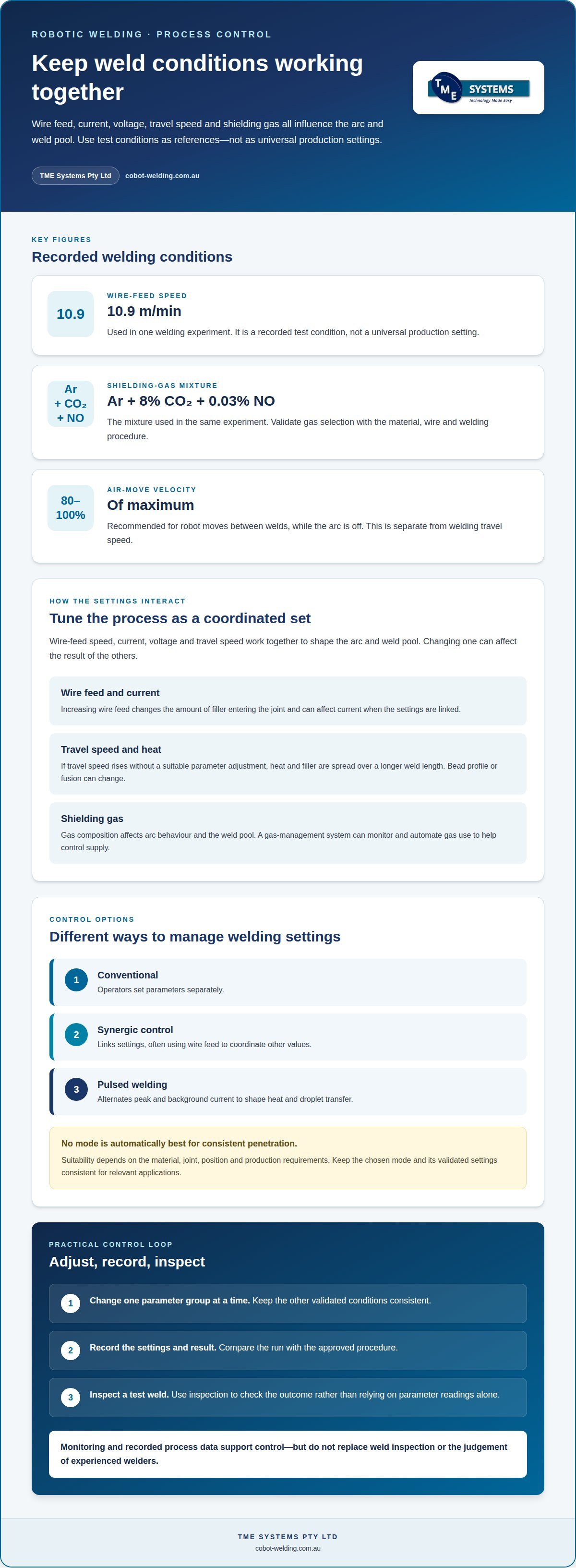
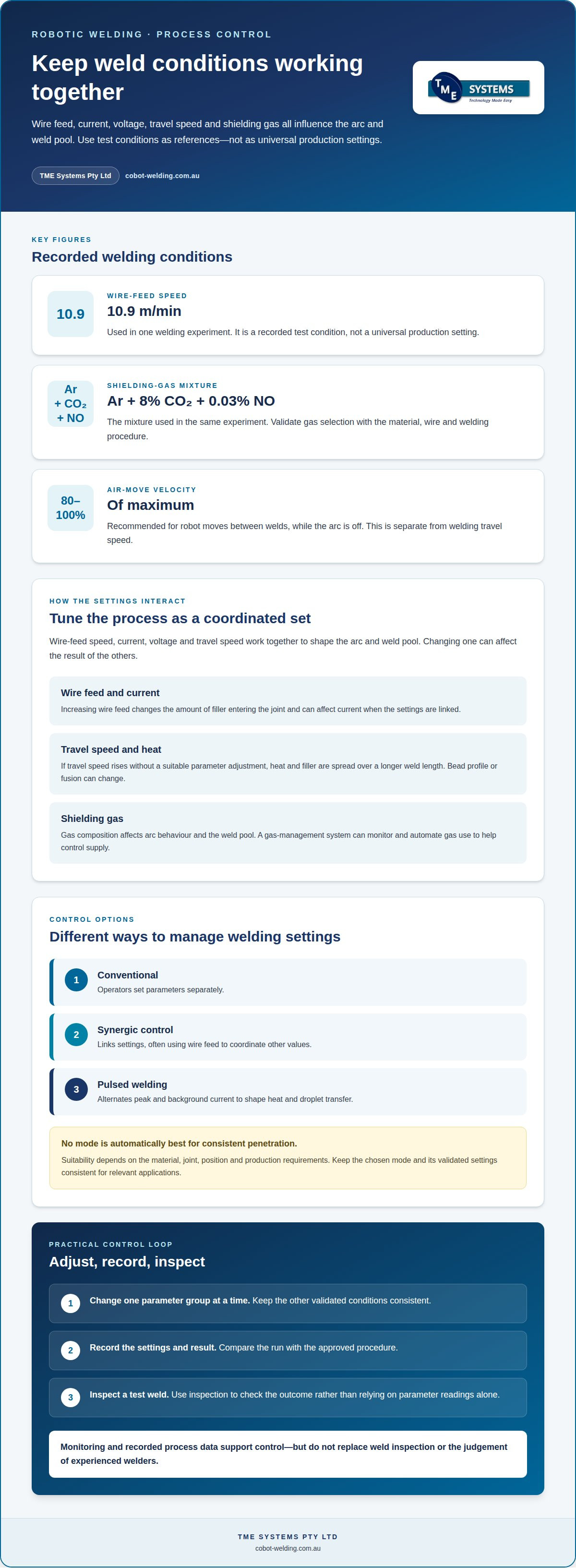
Wire feed speed, current, voltage and travel speed work together to shape the arc and weld pool. Increasing wire feed changes the amount of filler entering the joint and can affect current when these settings are linked. If travel speed rises without a suitable parameter adjustment, heat and filler are spread over a longer weld length. This can change the bead profile or cause insufficient fusion. Adjust the welding process as a coordinated set, then inspect a test weld.
Conventional processes let operators set parameters separately. Synergic control links settings, often using wire feed to coordinate other values. Pulsed welding alternates peak and background current to shape heat and droplet transfer. No mode is automatically best for consistent penetration: suitability depends on the material, joint, position and production requirements. Keep the selected mode and its validated settings consistent for the relevant applications.
One welding experiment used a wire feed speed of 10.9 m/min and a shielding gas mixture of Ar+8% CO2+0.03% NO. Treat these as recorded test conditions, not universal production settings. Gas composition affects arc behaviour and the weld pool, so validate the selected mixture with the material, wire and procedure. A gas-management system can monitor and automate gas use, helping control supply to the process.
Separate welding travel speed from air-move speed. Travel speed influences arc time and heat input along the joint; changes can alter penetration and bead formation. Air moves happen between welds, with the arc off. For clear robot movements, the recommended air-move velocity is 80-100% of maximum. This can shorten non-welding movements without changing the qualified weld travel speed. In industrial production, that distinction supports both precision and reliability.
For each adjustment, change one parameter group at a time, record the resulting values and inspect the weld. Compare current, voltage, wire feed and travel speed with the approved baseline. This gives the team a practical way to trace process changes and refine settings for the specific joint.
4. Repeatable weld paths and penetration
Consistent penetration depends on more than the robot repeating coordinates. Joint fit-up, fixture position, material condition, torch orientation, travel speed and arc parameters all affect how heat reaches the joint. Automation repeats the programmed path, so variation in a part or fixture can reproduce the same error throughout production. To achieve consistent weld penetration with robots, first stabilise how each component is located, then validate the path against real parts.
The path should direct the wire towards the intended joint through starts, corners and stops. If the root shifts between components, the same programmed movement may produce a different bead or fusion result. In GMAW, inconsistent penetration can also stem from changes in wire feed, voltage, current, contact-tip condition or shielding-gas delivery. Identify the likely cause before adjusting the program: correct location or workholding issues first, then review process settings and consumables.
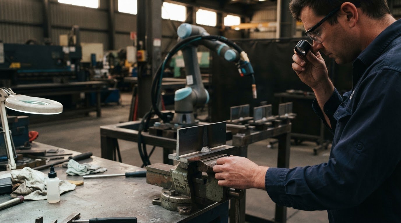
Use a representative part to confirm that the robot reaches the joint, maintains the intended torch orientation and follows a steady path. Inspect the weld against the relevant acceptance criteria, then adjust the path or parameters as needed. Once the result is approved, preserve the program and document subsequent revisions. The key to achieving consistent weld penetration with robots is to link each change to its observed effect, rather than making several adjustments at once.
Repeatability also relies on the welding system around the robot. Fixture wear, loose workholding or inconsistent component presentation can undermine a well-taught path. An external positioner can present a joint more consistently to the torch. During continuous manufacturing, review inspection results for recurring defects and address their cause. This helps welding systems support reliable fabrication, not simply repeat a movement. To develop repeatable paths through robotic welding integration, take the next step and explore how system integration can support your process.
TME Systems: Collaborative Robot Welding Cells
TME Systems Pty Ltd helps Australian manufacturers bring repeatable robotic welding into production with collaborative robot welding cells and welding system integration. When weld paths need to be taught or adjusted, its no-code teaching software lets operators make those changes without writing code.
The setup needs to suit the parts, joint access, fixtures and production workflow. TME Systems Pty Ltd integrates welding systems around these requirements, and its Mobile Demo System lets teams see the technology in action. Operator knowledge remains central to teaching paths and refining the process.
If you’re considering robotic welding for your production needs, contact TME Systems Pty Ltd to discuss your application.
Plan a practical next step for your production line
The next step in achieving consistent weld penetration with robots is to choose a production task where a controlled, repeatable process can make a practical difference. Start with a representative component, a recurring production challenge and the quality outcome that matters to downstream operations. This gives operators, welding personnel and quality staff a shared basis for evaluating the change.
Then map how the task fits into your workflow. Consider who will teach and maintain the program, how components reach the welding station, and how the process fits with existing operations. A focused trial can reveal constraints around access, handling and operator interaction before you plan a wider rollout. It also helps clarify what support the system needs for the job.
Robotic welding should fit the work and the people doing it. A considered next step can help your team assess the application without losing sight of day-to-day production priorities. Discuss your welding needs with TME Systems Pty Ltd and explore an approach suited to your production requirements.
Frequently Asked Questions
How should a robot be programmed and calibrated to maintain consistent torch angle, stick-out and travel speed?
Calibrate the tool centre point, then confirm torch orientation and wire extension against a representative joint. Program approach, weld and exit moves so the torch maintains clearance without changing its working angle. Run a test pass and inspect the bead before saving the production program. After a torch change or collision, recalibrate and recheck the path: even small shifts in tool position can affect where the wire meets the joint.
How do joint fit-up, gap, edge preparation and part tolerances affect robotic weld penetration?
Joint geometry affects what the arc must fuse. A wider root gap, uneven edge preparation or misaligned parts can leave the robot following its programmed path while the wire sits off-centre. For example, a fixture that locates one edge consistently but allows the opposite edge to move can create variable root conditions. Control fit-up and locate parts from stable datums. If variation remains, consider sensing or revise the procedure and path.
How can seam tracking and through-arc sensing compensate for part variation?
Seam tracking uses a sensor to locate the joint and adjust the robot’s path as the seam shifts. Through-arc sensing uses changes in the welding arc, commonly during a weave, to infer joint position and correct the path. These approaches can accommodate some positional variation, but they cannot correct poor edge preparation or a gap outside the qualified process range. Their effectiveness depends on sensor setup, joint geometry and arc stability.
What sensors and inspection methods can measure weld penetration in robotic welding?
Process sensors can record current, voltage and wire-feed behaviour, but these readings indicate welding conditions rather than directly measuring penetration depth. A cross-section of a cut and prepared sample can show fusion through the joint. Ultrasonic or radiographic testing can assess internal weld condition without sectioning the component, while visual inspection checks the surface. Select inspection methods to match the weld’s acceptance requirements and the evidence needed.