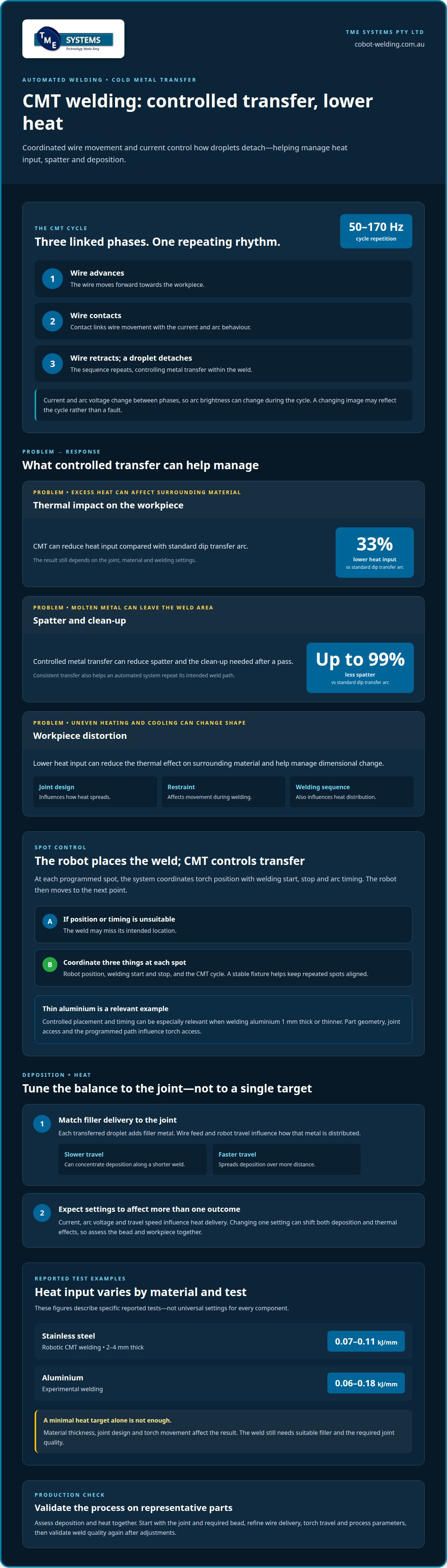

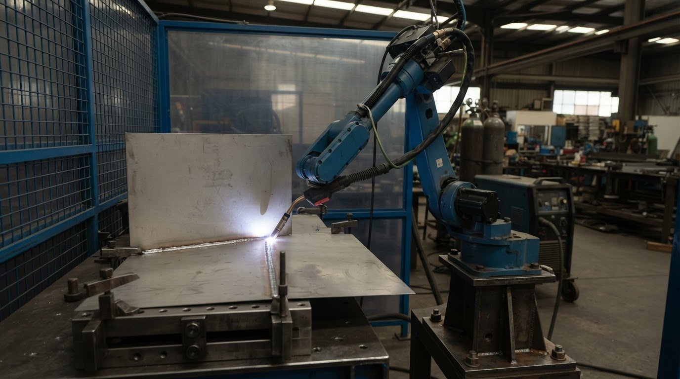
The arc isn’t the only part of CMT that controls the weld. In an automated CMT welding process, the wire feeds forward, retracts when it makes contact with the workpiece and detaches a droplet, helping manage heat and metal transfer. This cycle repeats at 50-170 hertz, so deposition can be controlled through the interaction between the wire, current and arc.
If you’re asking what the automated CMT welding process is, it uses controlled short-circuit metal transfer to keep droplet release steady while limiting heat during the arc cycle. That can help when a job needs consistent deposition or careful heat control around sensitive material.
This article explains how the CMT cycle works, how its phases affect heat input and deposition, and what spot control means in automated welding. It also covers potential applications and practical factors to assess before introducing the process into production.
Key Takeaways
- Understand how controlled droplet transfer can help manage heat and spatter, especially when working with thinner materials.
- See how changes across the CMT cycle affect spot control and the consistency of each weld.
- Learn which process factors influence deposition and heat, and why they matter when adapting CMT to a production task.
- Explore where CMT is used across industries and what to consider when assessing its fit for automated welding.
Controlled droplet transfer and low heat input
Cold metal transfer (CMT) controls droplet release through coordinated wire movement and current. Compared with standard dip transfer, this can reduce heat input and spatter.
Managing heat input
Heat input is the energy transferred into the workpiece during welding, affecting the weld and surrounding material. CMT reduces heat input by 33% compared with standard dip transfer arc. For production, this difference matters when limiting thermal impact is important, such as when joining thin sections. The result still depends on the joint, material and welding settings.
Reducing spatter
Spatter is molten metal expelled from the weld area rather than deposited in the joint. CMT can reduce spatter by up to 99% compared with standard dip transfer arc. Lower spatter can mean less weld-area clean-up after a pass. For an automated cell, consistent transfer also helps the system repeat the intended weld path without relying on manual correction between components.
Limiting workpiece distortion
Workpiece distortion is a change in shape caused by uneven heating and cooling during welding. Lower heat input can reduce the thermal effect on surrounding material, which matters when parts need to retain their dimensions. CMT can help manage heat, but results also depend on joint design, restraint and welding sequence, which all influence how heat spreads through an assembly.
Compared with MIG, CMT is a controlled metal-transfer approach; TIG uses a different arc-welding method. The suitable process depends on the material, joint and production requirements, not speed alone.
Australian standards, welding qualifications and workplace safety controls depend on the job, material and cell setup. Applicable requirements should guide the welding procedure, operator capability, and controls for robot movement and welding hazards.
An automated CMT cell needs a compatible welding power source, wire-feeding equipment, a torch, and a robot or other motion system. Fixtures hold the workpiece in position during welding.
Potential benefits include less spatter and lower heat input than standard dip transfer. Productivity and cost outcomes depend on the component, cycle and production setup.
Cell setup involves integrating the equipment, teaching the weld path, setting process parameters and validating weld quality on representative parts. After any adjustment, validate the weld again.
Possible defects include inconsistent welds and excess spatter; heat can also distort the workpiece. Process checks and risk controls should address the specific cell, material and welding task.
CMT Cycle Step and spot control
The CMT cycle is divided into three phases, linking wire movement with arc behaviour. During the sequence, the wire advances, contacts the workpiece and retracts, helping detach a droplet. The cycle repeats at 50-170 hertz. That repeated timing gives the process a controlled rhythm for automated welding, while current and arc voltage change between phases.
These electrical changes affect arc brightness, so the arc does not look equally bright throughout every cycle. For a camera or operator observing the process, a changing image may reflect the cycle rather than a fault. Spot control adds another layer by coordinating where the robot starts and stops welding, and how long the arc is applied at each programmed location.
For example, when a robot welds separate attachment points, it follows a programmed position for each spot. The system coordinates torch location and arc timing, then moves to the next point. If position or timing does not suit the component, the weld may miss its intended location. CMT’s repeated cycle controls metal transfer within the weld, while the robot path determines where the weld is placed.
On thin aluminium, including material 1 mm or thinner, controlled placement and timing can be especially relevant to the weld result. The part geometry, joint access and programmed path all influence how the torch reaches each location. A stable fixture also helps keep the workpiece aligned, so repeated spots follow the intended positions across a production run.
In practice, spot control is not a single setting. It is the coordination of the robot’s position, the welding start and stop, and the CMT cycle at each location. A collaborative robot welding cell brings robot motion and welding equipment together, supporting a coordinated setup for repeatable tasks. The operator still plays a practical role by teaching paths and refining the process for the component.
CMT Cycle Step deposition and heat control
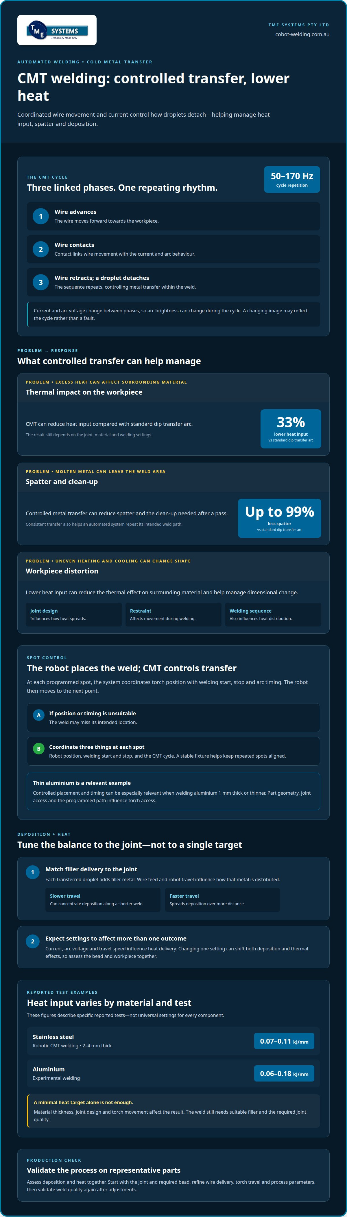
In CMT, deposition depends on how much wire reaches the joint and how the torch moves along it. Each transferred droplet adds filler metal, while wire feed and robot travel influence how that metal is distributed. Slower travel can concentrate deposition along a shorter weld; faster travel spreads it over more distance. The aim is to match filler delivery to the joint, not simply maximise deposition.
Heat control is part of that balance. Current and arc voltage change across the CMT phases, influencing the energy delivered during operation. Travel speed also affects heat input along the weld. A change in one setting can shift both deposition and thermal effects, so process refinement should consider the bead and workpiece together. This matters in robotic welding, where a repeatable path must suit the material and joint geometry.
Reported robotic CMT welding of stainless steel 2-4 mm thick used heat input of 0.07-0.11 kJ/mm. Experimental aluminium welding used a broader range, 0.06-0.18 kJ/mm. These figures describe specific tests, not universal settings for every component. Material thickness, joint design and torch movement all affect the result. They show why a minimal heat target alone is not enough: the weld must still receive suitable filler and achieve the required joint quality.
For production, assess deposition and heat together on representative parts. Start with the joint and required bead, then refine wire delivery, torch travel and process parameters. Check whether the deposited metal fills the joint consistently and whether heat affects the surrounding material. An aluminium component and a stainless-steel component, for example, may need different parameter combinations even when both use CMT. Considering these factors together makes each adjustment purposeful and helps the robot repeat a validated weld path.
CMT applications across industries
Cold metal transfer has been used across a wide range of industries for two decades. Applications include robotic joining and cladding, where controlled filler deposition can support different production requirements. Suitability depends on the material, joint design and required weld, not the industry label alone.
Which materials and thicknesses can be welded using automated CMT? Robotic CMT trials have tested aluminium alloy and stainless-steel sheets from 1.5-4.0 mm thick. CMT can also produce welds on aluminium 1 mm or thinner, making it relevant to thin-sheet work.
Cladding is another distinct application. CMT cladding can reduce metallurgical mixing between the base and filler materials by up to 75%, and is promoted as offering a 50% increase in welding speed. These figures describe cladding applications, not a guaranteed result for every material or component. They illustrate why CMT may suit work where limiting dilution and maintaining deposition control matter.
What are typical CMT welding parameters for different materials and applications? There is no single setting for every job: wire diameter, travel speed and process settings vary with the material, thickness and joint. One set of welding experiments used 1.0 mm solid wire and tested gun travel speeds from 7-25 mm/s; its stainless-steel results identified 10-12 mm/s as the most appropriate range.
Study values are useful reference points, not universal production settings. A robot path that suits stainless-steel sheet may need adjustment for an aluminium alloy component, joint access or cladding task. The application defines the target deposition and weld profile; parameter selection must then support those requirements consistently along the programmed path.
For repeatable production tasks, an integrated robotic setup coordinates torch movement with the CMT power source. Explore collaborative robot welding cells as an option for applying CMT in automated welding.
TME Systems
TME Systems helps Australian manufacturers assess and integrate robotic CMT welding around their production tasks. If your team is weighing repeatable weld paths, deposition control and operator involvement, the next step is matching the process with a practical cell configuration.
Collaborative robot welding cells combine robot movement and welding equipment, while TME Systems’ integration services connect system components to the application. No-code teaching software lets operators teach weld paths and adjust them without writing code. The Mobile Demo System brings a portable welding cell to your site for hands-on evaluation of how robotic welding could fit your workflow.
The right approach starts with the component, weld requirements and how operators will work with the system. TME Systems can help you assess these factors, integrate with existing welding equipment and workflows, and train operators. Contact TME Systems to discuss your automated welding requirements.
Plan the next step for your welding cell
Moving from process research to production starts with the part itself. Identify which welds need repeatable control, the operator’s role, and how the cell must fit the existing workflow. These priorities provide a practical basis for assessing whether an automated CMT welding process suits your operation.
The next step is a conversation about your components, production goals and integration needs. TME Systems can help you consider a suitable setup, keeping the operator’s experience central as the system is planned.
Contact TME Systems about CMT welding to discuss your application and explore a practical way forward.
With a clear production need and a considered approach, automation can extend your team’s welding capability.
Frequently Asked Questions
What Is CMT Welding?
CMT, or cold metal transfer, is an arc-welding process that controls how filler wire transfers into the weld. The name describes its reduced heat transfer compared with conventional dip transfer, not a process without heat. During operation, the wire briefly contacts the workpiece and retracts, helping detach the molten droplet. This controlled transfer can help where managing heat and spatter matters.
What is the automated CMT welding process and how does it work?
An automated CMT welding process combines a CMT power source and wire feed with a robot that follows a taught weld path. The system coordinates torch movement and the welding cycle along the joint. For a production change, an operator can teach or adjust the path, then assess the weld on a representative part. This approach suits repeat tasks when the workpiece can be positioned consistently.
How does automated CMT compare with MIG, TIG and other robotic welding processes?
CMT coordinates wire movement and current to control droplet transfer; compared with standard dip transfer arc, it reduces heat input by 33% and spatter by up to 99%. TIG uses a different arc-welding method, and the suitable process depends on the material, joint and production requirements.