
Robotic welding downtime often starts with maintenance issues: worn contact tips or nozzles, spatter build-up, or damaged cables and sensors can interrupt production and affect weld quality. A practical approach to reducing robotic welding downtime is to spot these signs early and plan checks around the cell’s operating needs. Replacing consumables before they fail can also help avoid stoppages and defects.
When a cell stops, the cause isn’t always an obvious breakdown. Small changes in wire feeding, torch condition or robot movement can be early clues, so routine checks matter on a busy workshop floor. This guide explains common causes of downtime, what to look for when inspecting key components, and when torch cleaning can support more continuous operation. You’ll also see how consistent maintenance and well-planned production can help keep avoidable interruptions from becoming part of the shift.
Key Takeaways
- Build consumable checks into planned maintenance, and watch for spatter or wear that could affect weld quality.
- Inspect cables, sensors and torch condition regularly; changes in wire feeding can point to wear or setup issues.
- A torch cleaning station can help manage spatter build-up, particularly when cleaning needs recur during production.
- Use operating and fault patterns to refine maintenance timing and plan production around servicing.
1. Q: What causes downtime in a robotic welding cell?
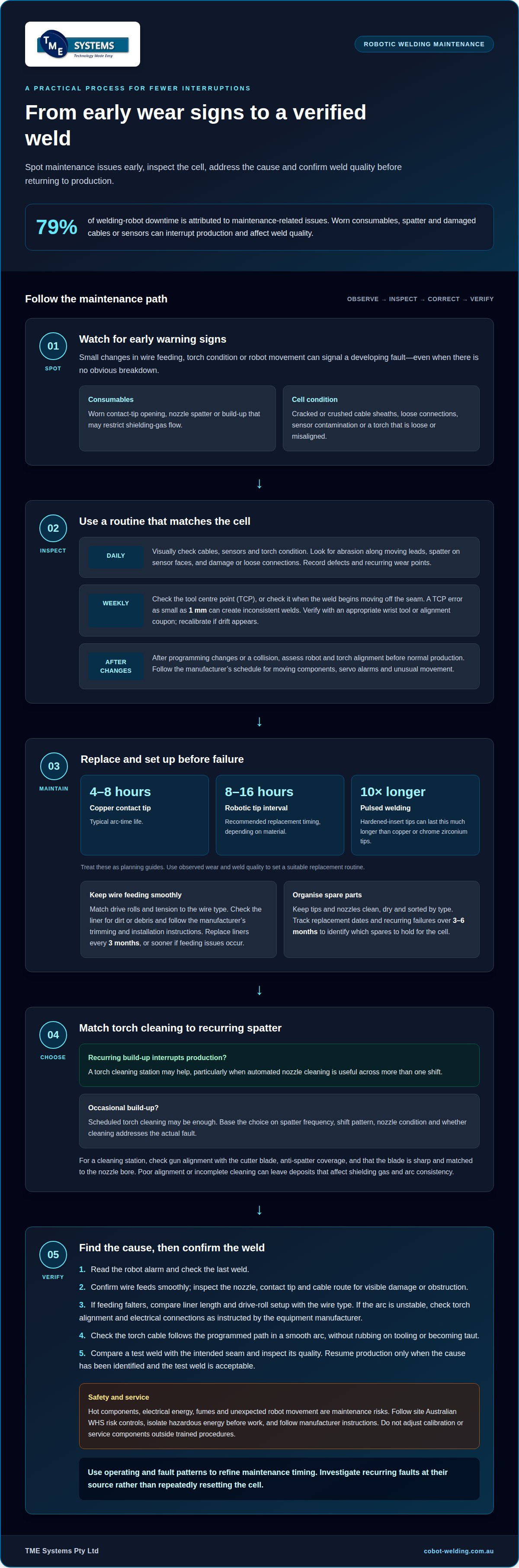
Maintenance-related issues account for 79% of welding-robot downtime. Common triggers include excessive spatter, worn contact tips and clogged or damaged nozzles. These consumables affect shielding gas and wire transfer, so a small wear issue can lead to weld defects, rework or an unplanned stop.
Contact-tip life depends on the material and welding conditions. A typical copper tip lasts 4-8 hours of arc time, while recommended replacement intervals for robotic welding contact tips are 8-16 hours, depending on the material. For pulsed welding, tips with a hardened insert can last 10 times longer than copper or chrome zirconium tips. Treat these figures as planning guides, then use observed wear and weld quality to set a suitable replacement routine.
Replace tips and nozzles before they fail or create defects. Check for a worn tip opening, spatter around the nozzle and any build-up that could restrict gas flow. Check nozzles for spatter buildup that could restrict gas flow. A planned change during a maintenance stop is easier to schedule than a failure during production.
Consumable management starts with clear storage and stock control. Keep tips and nozzles clean, dry and organised by type, so the operator can select the correct part without mixing sizes. Track replacement dates and recurring failures over 3-6 months; that record helps identify which spares need to be held for the cell.
Robots can produce precise, repeatable welds and reduce rework linked to human variation. However, consistent output still depends on timely consumable changes, planned maintenance and parts that suit the process.
Maintenance risks include hot components, electrical energy, fumes and unexpected robot movement. Follow the site’s Australian WHS risk controls, isolate hazardous energy before working and follow the robot and welding-equipment manufacturers’ maintenance instructions.
2. Checking cables, sensors and welding torches for wear
A daily visual inspection can catch cable, sensor and torch damage before it disrupts a shift. Look for cracked cable sheaths, crushed sections, loose connections and abrasion where the torch lead moves with the robot. Check sensor faces for spatter or contamination, and confirm the torch is secure and aligned. Record defects to identify recurring wear points and plan maintenance. These checks help reduce robotic welding downtime by catching faults early.
Check the tool centre point (TCP) weekly, or when the weld begins moving off the seam. A TCP error as small as 1 mm can create inconsistent welds. Use the appropriate wrist verification tool or alignment coupon, then recalibrate if drift appears. After any programming change or collision, assess robot and torch alignment before returning to normal production.
Wire-feed problems need a separate check. Match drive rolls and tension settings to the wire type; incorrect settings can deform wire or let it slip. A two-finger test can help identify poor feeding. Inspect the liner for dirt or debris, and follow the manufacturer’s instructions for trimming and installation. A liner cut too short can disrupt feeding; replace liners every 3 months, or sooner if feeding issues occur.
Preventive maintenance helps reduce downtime by identifying wear before it causes a stoppage. Follow the robot manufacturer’s schedule, including daily visual checks and recommended inspections of moving components. Review servo motor alarms and unusual movement, then follow manufacturer guidance to investigate. Don’t adjust calibration or service components outside trained procedures.
Before production, check that the torch, cables and sensors are in sound condition, wire feeds smoothly and the TCP matches the programmed weld position. Compare a test weld with the intended seam location and inspect for signs of inconsistent quality. To reduce robotic welding downtime, investigate recurring faults at their source instead of repeatedly resetting the cell.
3. Q: Should I use a torch cleaning station for my welding robot?
A torch cleaning station may help when spatter repeatedly builds up around the nozzle and interrupts production. Automated nozzle cleaning can be useful for operations running more than one shift, but it will not fix every stoppage. Check gun alignment with the cutter blade, anti-spatter coverage, and whether the blade is sharp and matched to the nozzle bore. Poor alignment or incomplete cleaning can leave deposits that affect shielding gas and arc consistency.
After a stoppage, start with the robot alarm and the last weld. Check that wire feeds smoothly, then inspect the nozzle, contact tip and cable route for visible damage or obstruction. If wire feed falters, compare liner length and drive-roll setup with the wire type. If the arc is unstable, check torch alignment and electrical connections according to the equipment manufacturer’s instructions. Resume production only after identifying the cause and confirming the test weld is acceptable.
Heat issues need a cooling check. Air-cooled and water-cooled robotic MIG torches suit different current and duty-cycle demands. Air-cooled torches rated at 500 amps are described as operating comfortably at 200 to 300 amps with mixed gases and approximately 100 per cent duty cycle. Water-cooled MIG torches are described as handling 300 to 600 amps at 100 per cent duty cycle. Match torch capacity to the process rather than treating cleaning as a fix for overheating.
Inspect the torch cable as the robot moves through its programmed path. It should leave the gun’s front housing in a smooth arc, without rubbing against tooling or becoming taut. A cable that catches at a joint can strain connections and interrupt the cycle.
Consider a cleaning station if recurring spatter makes manual cleaning a frequent interruption. For occasional build-up, scheduled torch cleaning may be enough. Choose based on spatter frequency, shift pattern, nozzle condition and whether cleaning addresses the actual fault.
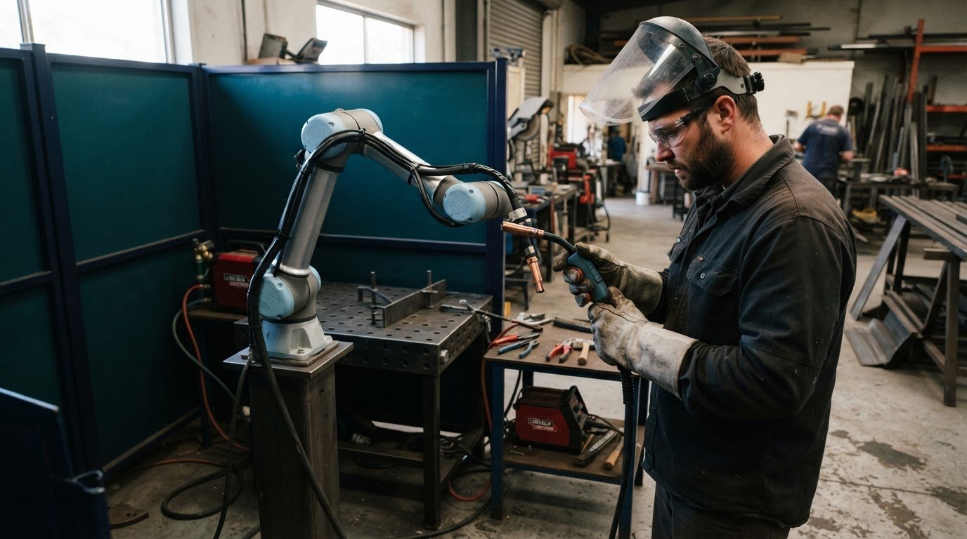
4. Continuous robotic welding operation
Continuous operation depends on managing the whole cell, not just keeping the robot moving. Robotic welding systems can produce welds 24/7, but production still relies on part loading, consumable changes and planned maintenance. A dual-station layout can let an operator unload one workpiece and load the next while the robot welds at the other station. That workflow reduces idle time without removing the operator from quality checks or material handling.
Plan production so routine stops are predictable. Use the robot’s cycle time and the manufacturer’s maintenance schedule to place inspections between jobs or shifts. Include the torch, cables, fixtures and nozzles in planned checks. If nozzle cleaning or a consumable change repeatedly interrupts production, record when it happens and adjust the maintenance window to suit the pattern.
Robot movement matters too. Review the program for unnecessary travel between welds, then confirm each path allows access and clearance around the fixture. Poor part positioning or inconsistent clamping can cause path deviations and repeated defects. Repeatable locating features help operators position each workpiece consistently, while a test run can reveal collisions before production resumes.
Track practical measures such as arc-on time, cycle time, consumable replacement frequency, fault frequency and production output. Review the records when troubleshooting. For example, more faults alongside longer cycle times may indicate recurring interruptions that need investigation. Use the findings to refine maintenance timing, identify component issues and organise spare parts around the cell’s actual needs.
Continuous welding is a coordinated routine: operators load parts, inspect key components, follow planned servicing and use production data to adjust the process. To plan a cell around your production workflow, discuss your robotic welding setup.
TME Systems: Collaborative Robot Welding Cells
TME Systems helps Australian manufacturers adopt collaborative robot welding for repeatable welding tasks. Its no-code teaching software lets operators teach weld paths and adjust parameters without writing code, keeping their process knowledge central to cell operation. TME Systems also provides welding system integration to connect the technology with existing equipment and workflows.
If you’re assessing a first collaborative welding cell or refining a welding workflow, TME Systems’ Mobile Demo System brings a welding cell to your site for a demonstration. Integration planning considers how parts, fixtures and operator tasks fit into production.
For a practical discussion about your welding operation, contact TME Systems Pty Ltd.
Plan your next step towards steadier production
Reducing robotic welding downtime takes ongoing attention, not a one-off equipment adjustment. Map where interruptions affect production, then identify which changes belong in maintenance routines, operator processes or cell setup. This gives your team a practical basis for deciding what to address first.
Bring your production requirements and the challenges operators encounter to the discussion. The parts you weld, how they are presented to the cell and how people interact with the equipment all shape a workable setup. TME Systems can discuss your parts, production goals and whether an on-site demonstration would help you assess a collaborative welding approach.
Contact TME Systems Pty Ltd to discuss your welding needs and explore a practical next step for your production floor.
Frequently Asked Questions
What causes downtime in a robotic welding cell?
Downtime can follow maintenance issues, worn consumables, spatter build-up, wire-feed faults or a collision. Gas supply problems or a fixture that places a part outside its expected position can also stop a cell. Compare the fault message with recent inspection notes and the affected weld to distinguish a recurring component issue from a setup problem.
How do you stop contact tips from cross-threading in a robotic MIG gun?
Start the tip squarely by hand and turn it gently before using a tool. If it does not engage smoothly, stop and check the tip and gun threads for spatter, debris or damage rather than forcing it. Confirm the tip is the correct type for the torch. Correct alignment during installation helps protect the threads and makes future consumable changes easier.
How often should I replace welding robot contact tips and nozzles?
Plan to replace robotic welding contact tips every 8-16 hours, depending on the material, and replace nozzles weekly or sooner if spatter affects gas flow. Standard copper tips typically last 4-8 hours of arc time. Use visible wear, wire-feed behaviour and weld condition to refine the schedule for your process, and change parts before they cause defects or stop production.
How often should a nozzle cleaning station ream and spray?
Set the cleaning cycle to remove spatter before it restricts gas flow or affects the next weld, then review the timing against nozzle condition and production results. A cycle that runs too rarely can leave deposits, while unnecessary cycles add interruptions. Check that the cutter is sharp and suited to the nozzle bore, and that anti-spatter coverage reaches the nozzle consistently.
Should I use a torch cleaning station for my welding robot?
A cleaning station may be worth considering when recurring spatter makes manual nozzle cleaning disruptive, particularly for operations running more than one shift. It can help keep the nozzle clear, but will not resolve unrelated faults such as poor wire feeding, incorrect TCP or a damaged cable. Include station alignment, cutter condition and anti-spatter coverage in routine checks.
What should you check after a robot collision?
After a collision, return the robot to its home position and recheck the tool centre point and clutch before resuming welding. Inspect the torch, arm, cables and mounting for visible movement or damage, then confirm the torch aligns with the programmed path. A controlled test run can reveal a shifted position or new interference before loading production parts.