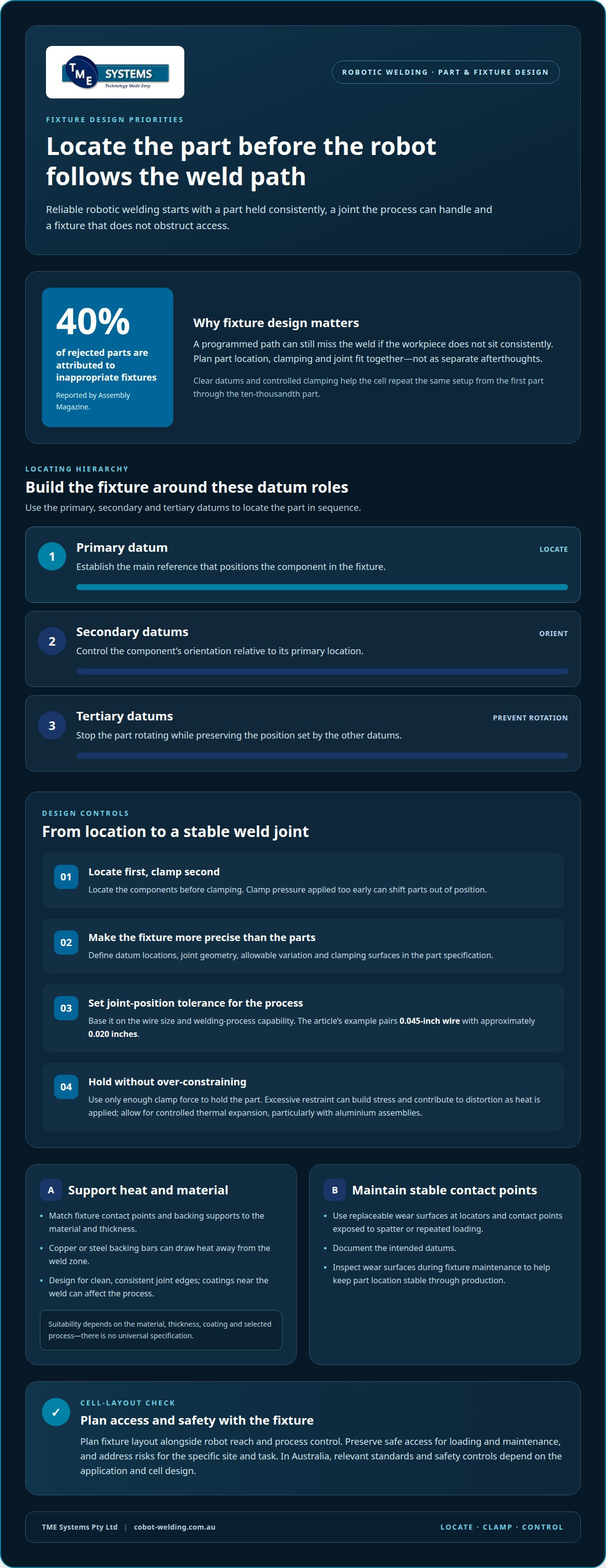

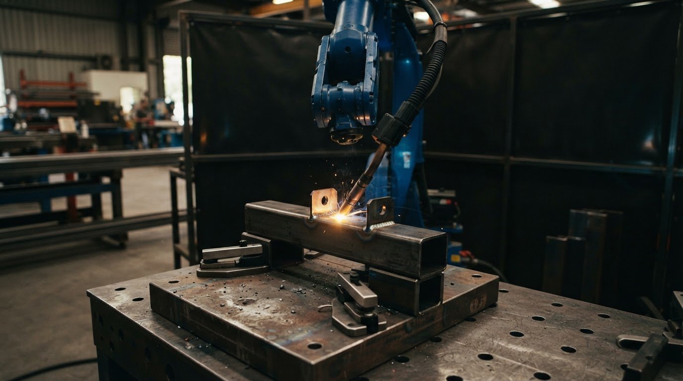
A robot can follow its programmed path and still miss a weld if the part doesn’t sit consistently in its fixture. Designing parts for robotic welding means considering the fixture, torch access and joint fit together, so parts are located reliably and the robot can reach each weld. Assembly Magazine reports that inappropriate fixtures contribute to 40 percent of rejected parts.
It’s easy to focus on robot reach or repeatability and leave part and fixture design until later. But datums, clamp placement, joint gaps and tolerances all affect whether the taught weld path aligns with the workpiece. Plan these relationships from the start.
This guide covers fixture fit, torch access and cable clearance, tolerance stack-up, joint gaps and the wider welding process. It also explains how positioners and quick-change fixtures can affect part design, so you can make practical decisions before setting up a cell.
Key Takeaways
- Use clear locating datums and controlled clamping to hold parts consistently without building unnecessary stress into the assembly.
- Plan torch approach and cable clearance around the actual weld path, then use CAD simulation to identify access problems before cell construction.
- Trace how part tolerances combine at each joint, since small position changes can affect whether the torch reaches the intended weld.
- Match cell components, such as positioners and teaching tools, to the part’s access and changeover needs.
1. What Makes a Fixture Work in a Robotic Welding Cell?
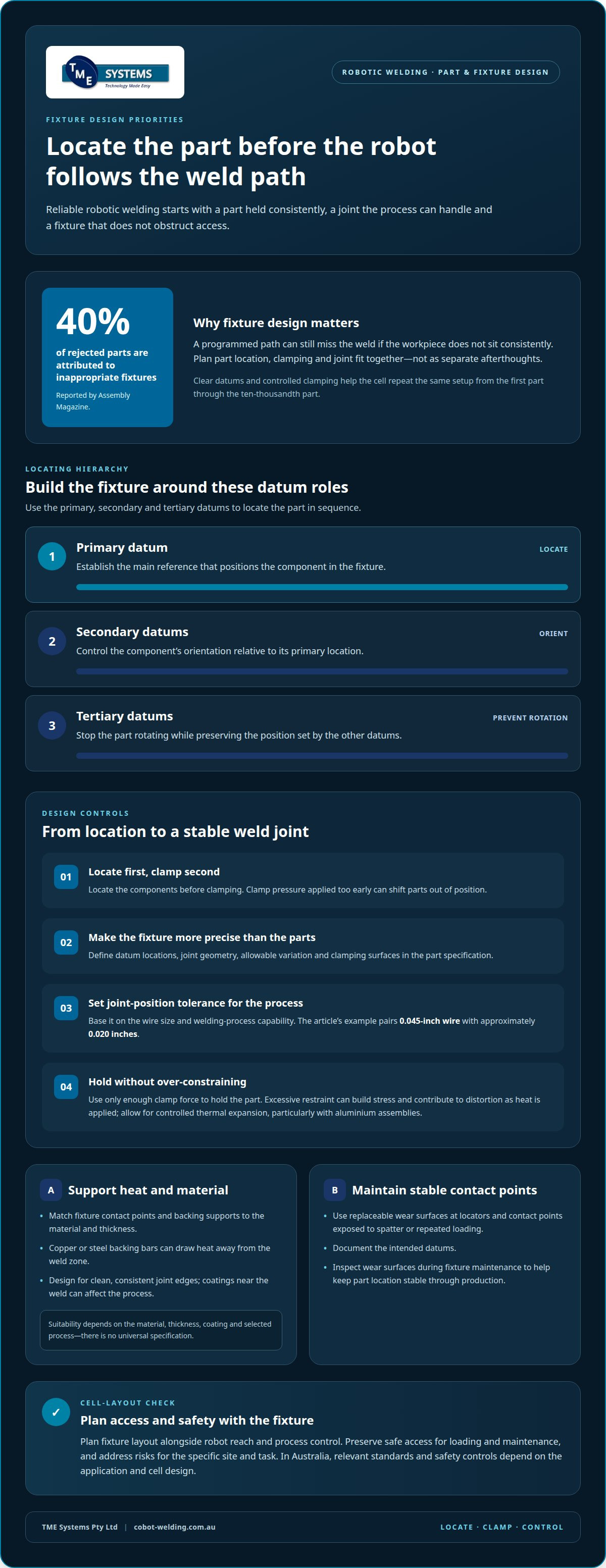
When designing parts for robotic welding, plan the fixture to locate components consistently while leaving the torch clear access to each joint. Clear datums and controlled clamping help a cell repeat the same setup from the first part through the ten-thousandth part. Assembly Magazine reports that inappropriate fixtures contribute to 40 percent of rejected parts.
Start with the part’s primary datum to locate it, then use secondary datums to control orientation and tertiary datums to prevent rotation. Locate components before clamping; otherwise, clamp pressure can shift them out of position. Keep the fixture more precise than the parts it holds, and specify the joint gap the welding process can tolerate. Set joint-position tolerance according to the wire size and the welding process’s capabilities. With 0.045-inch wire, the stated example gives approximately 0.020 inches.
For a robotic welding cell in Australia, relevant standards and safety controls depend on the application and cell design. Plan fixture layout alongside robot reach and process control, preserving safe access for loading and maintenance and addressing risks for the specific site and task.
A key step in designing parts for robotic welding is defining the part specification. Include datum locations, joint geometry, allowable variation and clamping surfaces. The fixture should support the workpiece without over-constraining it. Excessive restraint can build stress and contribute to distortion as heat is applied. Use only enough clamp force to hold the part, while allowing for controlled thermal expansion, particularly with aluminium assemblies.
Material and thickness affect heat flow and distortion, so choose fixture contact points and backing supports to suit the assembly. Copper or steel backing bars can draw heat away from the weld zone. Design for clean, consistent joint edges, and consider coatings near the weld because they can affect the process. Suitability depends on the material, thickness, coating and selected process; there is no universal specification.
Include replaceable wear surfaces at locators and contact points exposed to spatter or repeated loading. Document the intended datums and inspect these surfaces during fixture maintenance. This helps keep part location stable throughout production.
2. Torch access, cable routing and approach angles
A weld path is useful only if the robot can approach the joint with the torch correctly oriented. In CAD simulation, check the robot model, torch body and workpiece together. Run the full path to identify collisions and unreachable positions before building the cell.
Joint type and weld position determine how much access the torch has. A fillet weld inside a tight corner may leave less nozzle clearance than an exposed butt joint. If a flange blocks access, consider changing the part geometry, fixture opening or robot approach so the torch can reach the seam without striking surrounding material. Access from above, below or the side can also affect weld position and sequence.
Allow for the torch’s actual tool centre point, nozzle width and wire stick-out. Check clearance on both sides of the joint, including at the start and end of each weld. Test different workpiece orientations too: a path that clears in one position may collide when a positioner turns the part.
Plan the cable package around the robot arm’s movement. Route welding cables and torch leads to avoid snagging on the fixture, pinching against the workpiece or pulling the torch off its intended angle. Trace cable movement along the complete path, including changes in wrist orientation. Keep power supply connections accessible for setup and servicing, and separate cable runs from clamp and loading areas.
For repeatable weld quality, record the approved approach angle and torch orientation alongside the programmed path. A practical check is to simulate a narrow internal seam and an exposed external seam, then inspect clearance at every transition. This reveals whether the machine can maintain access without awkward wrist positions or pauses. Where automation planning needs a closer look, robotic welding system integration can help bring part access, robot movement and process requirements into the same design discussion.
3. Tolerance stack-up and joint gaps
For robotic welding, assess how each locating feature affects the assembled joint position. A part can meet its individual drawing tolerances yet sit out of line after forming, machining and assembly. Trace the measurement chain from the features that locate the component to the weld seam, then identify which dimensions contribute most to variation.
Set an acceptable joint gap for the selected welding process and joint type. The drawing should show where the gap is measured and which surfaces define it. A variable gap can change how the weld fills the joint, while inconsistent edge alignment can shift the seam away from the taught path. Design mating edges and locating features to control both.
Review the tolerance chain across the assembly, not just part by part. Record each contributing dimension, its tolerance and the direction in which it affects the joint. This helps distinguish critical dimensions from those with little effect at the seam. In high-volume production, that distinction can guide tighter controls where they matter without over-constraining every feature.
Use representative parts to check fit-up across expected manufacturing variation. Record the joint position and gap in the fixture, then compare the results with the limits established for the welding process. If fit-up varies, refine the feature causing the movement or change how the parts locate together. This links drawing tolerances to the actual assembled condition.
For complex assemblies, use CAD models and, where thermal movement matters, finite element analysis to support tolerance analysis. These tools help engineers examine how dimensional variation or heat may affect the joint before production. Use the model to identify sensitive areas, then validate the design with physical parts and the intended fixture. This connects design assumptions to real fit-up and helps support a repeatable welding process.
4. Robotic welding system components
A robotic welding system includes more than the robot arm. The torch, power supply, positioner, fixture and loading method all affect how the workpiece moves through production. A six-axis welding robot can position its torch within ±0.05 mm, but that precision depends on parts being presented consistently and the full cell supporting the programmed operation.
For long or multi-sided welds, a rotisserie table or headstock-tailstock positioner can rotate the fixture so the robot reaches different faces. A headstock-tailstock positioner can turn a fixture 360 degrees. That may let one setup present several welds to the torch, reducing the need to reposition the part manually between operations.
Changeover equipment matters when production includes different part variants. Automated quick-change systems can change fixtures in under a minute. Design repeatable mounting points so each change returns the workpiece to its intended position. Also consider whether a new fixture affects torch access, cable movement or the operator’s loading sequence.
Electrical and process components also shape the cell. Copper ground straps provide a clean return path for welding current. Touch sensing or seam tracking can adjust the robotic path within set limits to accommodate some joint variation. These functions support the process but do not replace consistent part presentation or a sound fixture. Spatter can affect torch consumables and fixture contact points, so allow access for cleaning and maintenance.
Finally, decide whether the operator loads parts directly or a material-handling robot presents them. A handling robot can automate presentation, but it also increases the operation’s cost and complexity. Map the loading sequence from the operator’s starting position through clamping, welding and unloading. This reveals whether a positioner, fixture change or handling step creates a bottleneck. To plan how these components work together, discuss welding system integration around your part and production sequence.
TME Systems: Collaborative Robot Welding Cells
TME Systems helps translate part and fixture requirements into a practical collaborative welding setup. Its welding system integration connects collaborative robot welding with existing welding equipment and production workflows.
For operators teaching weld paths or adjusting parameters without traditional programming, TME Systems’ no-code teaching software provides an operator-led way to set up the path. Its Mobile Demo System brings a welding cell to your site for a demonstration, helping your team see how the approach could fit your work.
If access, changeovers or operator workflows are shaping your cell design, TME Systems Pty Ltd can discuss how its offerings fit those requirements. Contact TME Systems Pty Ltd to discuss your application.
Plan the next step around a real part
Choose a representative part to guide the next design discussion. Bring the drawing, expected part variation, weld sequence and loading and unloading process. This gives the team a practical basis for discussing fixture fit, robot access and workflow together.
Designing parts for robotic welding works best when design decisions reflect how the cell will run day to day. Consider who will teach the weld path, how a part variant affects setup and what the operator needs to keep work moving. These details help turn an automation idea into a workable plan centred on the people using the equipment.
If you’re ready to explore how a robotic welding cell could fit your parts and process, contact TME Systems Pty Ltd to discuss the next step. A clear starting point can make the conversation practical and productive.
Frequently Asked Questions
What Makes a Fixture Work in a Robotic Welding Cell?
A fixture should present the part consistently and suit the jobs planned for the cell. A family of similar parts may share locating features, while variants need clear setup references to prevent loading the wrong configuration. Good early candidates also need repeatable fit-up, sensible torch access, stable fixturing and enough repeat work to justify teaching and proving the weld path.
What tolerances and fit-up gaps are recommended for robotic welding?
Set tolerances and fit-up gaps to suit the welding process, wire size and joint geometry. The joint position needs to repeat within half the wire diameter; the 0.045-inch wire example uses approximately 0.020 inches. A useful drawing should define the intended joint gap and the features controlling its position, so fabrication and assembly requirements support the same weld location.
How can part design reduce distortion, spatter, and weld defects?
Part design can help manage distortion by supporting a balanced weld sequence and avoiding unnecessary restraint. On a symmetrical assembly, alternating welds on opposite sides distributes thermal stress more evenly. Consistent tack-weld size and location can help hold the joint in place for the planned sequence. Design fixtures and access for practical spatter removal, since buildup around contact points can disrupt repeatable part presentation.