
What if the best way to reduce weld spatter is to stabilise the process before adding a robot? Spatter means more grinding, cleanup and inspection, but its cause isn’t always obvious. Eliminating weld spatter with automation starts with finding what’s driving it, not assuming a robot will fix it.
If you’re weighing up automation, ask whether a cobot will make weld quality more consistent or simply repeat an unstable process. Repeatable paths and controlled parameters can support consistency, but they work best after you understand and refine the welding process.
This guide covers likely sources of spatter, practical process checks and where automation may help. You’ll learn how no-code teaching lets operators make and repeat weld-path changes, and what to record in a controlled trial, from spatter and rework to weld quality and cycle time. Use that evidence to decide whether a collaborative welding cell suits the task.
Key Takeaways
- Trace spatter to the weld, material, consumables and process conditions before changing equipment.
- Inspect wire feed, consumable wear and shielding-gas delivery, then adjust one factor at a time.
- Compare process corrections, manual consistency measures and automation by the problem each addresses and its limitations.
- For a controlled trial, record a representative part’s settings and spatter baseline, then assess results after known faults are corrected.
- Eliminating weld spatter with automation depends on a stable process, with operator-taught paths helping repeat refined adjustments.
Why eliminating weld spatter with automation starts with finding the cause
Weld spatter is molten filler metal or base material expelled from the weld area and deposited nearby. Some particles come away easily; others cling to the workpiece, fixture or surrounding components. The visible mess is only part of the problem. Attached deposits can mean extra cleaning or grinding, additional inspection and delays before a part is ready for coating or assembly.
That makes eliminating weld spatter with automation a process question before it’s an equipment decision. A robot can repeat a taught weld path, but it won’t identify why the arc is unstable, remove contamination or correct unsuitable settings on its own. First establish what is happening in the current process and where spatter is affecting production.
When is weld spatter a production problem?
Not every deposit has the same impact. A small amount on a non-critical surface may be cosmetic, while spatter around a threaded hole can obstruct a fastener. Deposits on a fit-up face may interfere with assembly, and spatter where coating or inspection is required can add a removal or checking step.
Judge the issue against the part’s requirements and what happens next in the workflow. Recurring cleanup uses labour and abrasive consumables, and can interrupt the hand-off to another task. The relevant limit may be set by customer requirements, component function or downstream processes. A blanket “zero spatter” target may not be practical or necessary.
What can automation change, and what can it not?
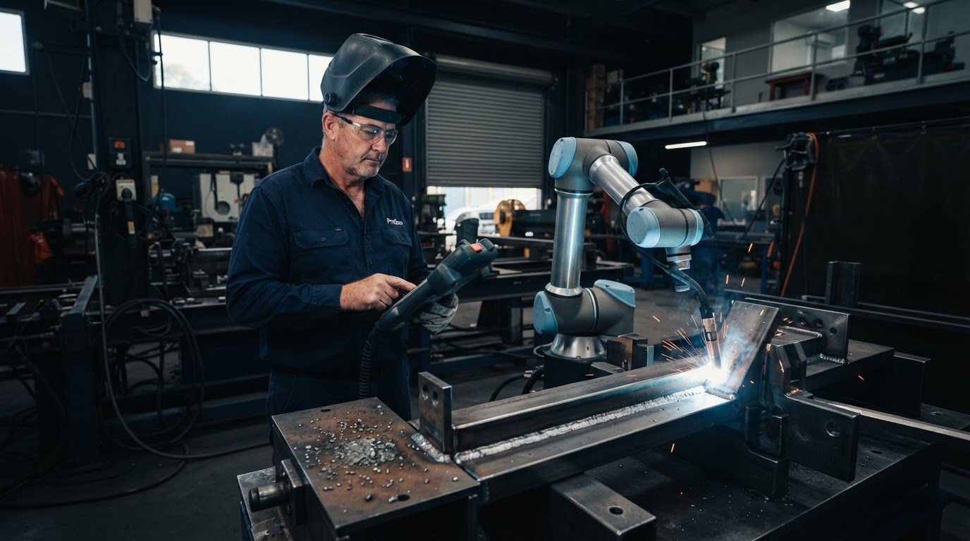
A programmed path can help keep torch position, angle and travel consistent from part to part. That repeatability is useful when variation in manual execution contributes to inconsistent results. Operators can teach and adjust weld paths using no-code teaching software, then repeat the refined movement without traditional programming.
Repeatable motion is not the same as a sound welding procedure. Automation won’t clean rusty or contaminated material, correct poor fit-up or validate settings that don’t suit the material and joint. Preparation and process decisions still matter, and an unsuitable setting can be repeated just as consistently as a suitable one.
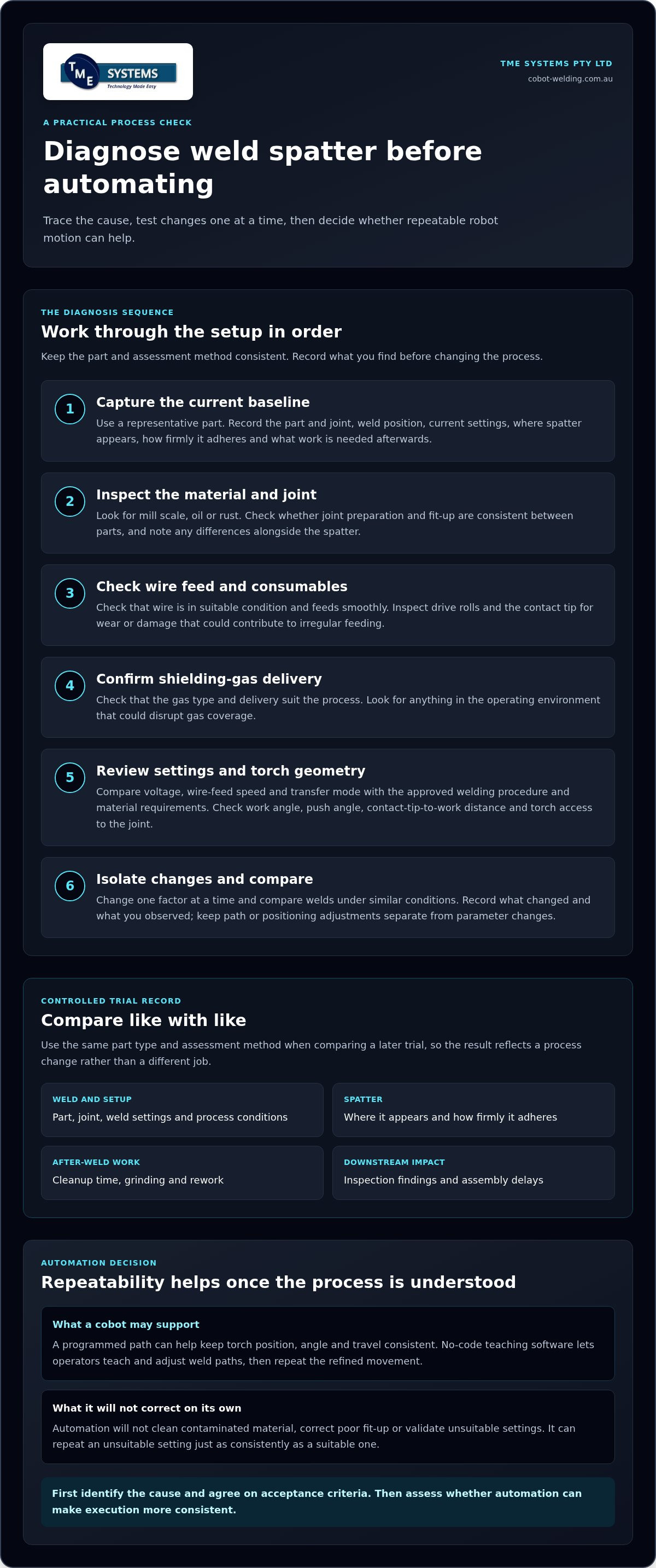
Before changing equipment, capture a baseline using a representative part and the current process. Record the weld settings, where spatter appears, how firmly it adheres and what work is needed afterwards. Include practical measures such as cleanup time, rework, inspection findings and assembly delays. Use the same part type and assessment method when comparing a later trial, so the result reflects a process change rather than a different job.
This gives the team a clearer starting point: is the main issue inconsistent execution, a process condition that needs attention, or both? Once you understand the cause and agree on acceptance criteria, you can assess whether automation may support more consistent execution rather than expecting it to solve an unstable process on its own.
How to diagnose the causes of spatter before automating a weld
A useful diagnosis starts with the whole weld setup, not the robot path alone. Record the part and joint, material condition, consumables, weld position and current settings. Note where spatter lands, whether it appears throughout the weld or in particular sections, and how much cleanup follows. The American Welding Society outlines welding as a process involving heat, materials and technique, which is why it pays to check these factors together before changing equipment.
Work through the checks in a consistent order and change one factor at a time. If you alter voltage, wire-feed speed and torch angle in the same trial, you won’t know which change affected the result. Compare each weld under similar conditions, then record what changed and what you observed. These notes give operators and engineers evidence to decide whether a process correction is needed or whether repeatable execution may help.
Check material, wire and shielding conditions
Start at the joint. Look for mill scale, oil, rust or differences in joint preparation between parts. Check that the wire is in suitable condition and feeds smoothly through the feed path. Inspect drive rolls and the contact tip for wear or damage that could contribute to irregular feeding. Confirm that the shielding-gas type and delivery suit the process, and check for anything in the operating environment that could disrupt gas coverage.
Include material and consumable checks in the trial record. If spatter changes between parts, note any difference in cleanliness, fit-up or wire feeding before adjusting settings. A programmed path can repeat the same movement, but it can’t remove contamination or make variable material preparation consistent.
Review settings, torch geometry and robot path
Compare voltage, wire-feed speed and transfer mode with the approved welding procedure and material requirements. Don’t treat a setting in isolation: the parameter combination and joint conditions both affect the weld. Check work angle, push angle and contact-tip-to-work distance, and whether the torch can reach the joint without an awkward approach.
For a robot trial, compare the taught path with the actual joint and fit-up. A mismatch between the programmed route and part position can affect where the arc meets the joint. Record any path or positioning adjustment separately from changes to welding parameters, so you can assess the effect of each.
A practical fault-isolation sequence is:
- Document the part, joint, weld position, current settings and observed spatter.
- Inspect material preparation, wire feeding, consumable condition and gas delivery.
- Compare the parameter combination and torch geometry with the approved procedure.
- Correct one identified issue, then repeat the weld under comparable conditions.
- Log the spatter location and amount, cleanup time, and any change made.
These records connect diagnosis to an automation trial. They show which conditions need to be controlled and which adjustments are worth teaching into a repeatable path. For a practical look at how a cobot can support consistent weld execution, explore collaborative robot welding.
Which spatter-reduction measures suit manual welding and automation?
Choose a measure based on the cause you’ve identified, not simply on whether the weld is manual or robotic. Correcting a process fault, helping an operator keep a steady technique and programming a repeatable path solve different problems. Use the comparison below to identify where each approach fits and what to check before relying on it.
| Measure | Problem it addresses | Limit | Practical check |
|---|---|---|---|
| Process correction | Contamination, inconsistent wire feeding, poor gas delivery or unsuitable parameter settings. | Requires an identified cause; changing several factors together makes results harder to assess. | Correct one issue at a time and compare welds under similar conditions. |
| Manual consistency controls | Variation in torch angle, position or travel between operators or welds. | Doesn’t remove variation in material, joint preparation or operator technique by itself. | Agree on a repeatable method and check welds across operators and parts. |
| Automated repeatability | Variation in taught torch movement, position and travel on suitable, repeatable work. | Repeats the path, but doesn’t correct a poor procedure, contamination or inconsistent fit-up. | Compare spatter, weld quality and cleanup across comparable parts. |
When process adjustments should come before automation
Address contamination, wire-feed irregularities, gas delivery and unsuitable settings before teaching a path. A stable, documented process gives manual welding or automation a sounder starting point. Changes such as pulsed MIG or a different consumable may suit some applications, but they need to be checked against the material, joint and welding procedure. Anti-spatter products can help with deposits in some circumstances; they don’t replace process control or weld-quality checks.
Technical guidance from TWI Global discusses spatter causes and reduction methods, reinforcing the value of matching a correction to the conditions producing the spatter. No single technique is a universal fix. For example, Bosch Rexroth reports a 90% reduction for its specific resistance spot-welding solution. That is a vendor- and process-specific result, not a general benchmark for arc welding, MIG processes or cobot cells.
Where a cobot may help repeat the improved process
Once the weld process is understood and refined, a cobot can repeat a taught torch path to support consistent movement from part to part. Operators can teach paths and adjust them without traditional programming. Results still depend on reliable part presentation: variation in fit-up, fixture quality or joint access can affect how well the taught path follows the weld. This guide to collaborative robot welding cells can help frame how a cell fits into the job.
The decision isn’t manual welding or automation at any cost. Match the measure to the cause first, then assess whether repeatable execution would address a remaining source of variation. That’s the practical starting point for eliminating weld spatter with automation without assuming a robot will fix every process issue.
How to run a controlled spatter-reduction trial with a welding cobot
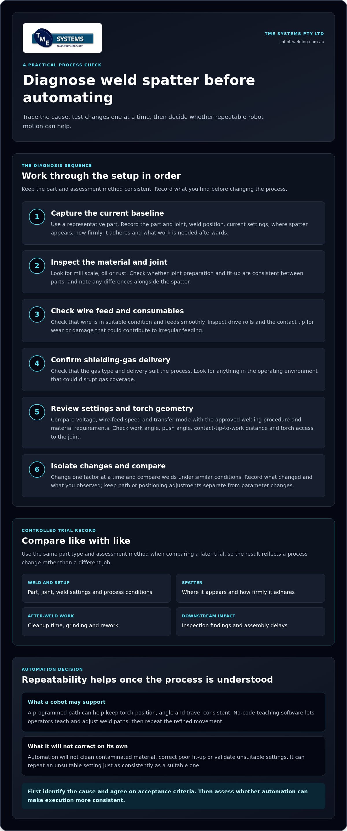
A useful cobot trial compares like with like. Choose a representative part that reflects normal material condition, joint preparation, fit-up and weld position. Document the existing process before teaching a robot path, and correct known faults first. Otherwise, a change in spatter could come from cleaner material or repaired wire feeding rather than the cobot.
Agree on what a successful trial means before welding begins. The aim might be fewer attached deposits, less cleanup, consistent weld acceptance, or a combination. Set practical measures that suit the job and can be recorded consistently by the people assessing the parts.
Set a useful baseline and success criteria
Record the current settings, consumables, part condition, fit-up and welding method. Note where spatter appears and how much cleanup each part needs. Agree how weld quality will be assessed against the applicable job requirements, so a cleaner-looking weld isn’t treated as a success if it fails acceptance checks.
Use the same inspection and recording method throughout the comparison. Include rework events, cleanup time and operator feedback, along with any production or cycle-time demands the cell must meet.
- Spatter: record its location and whether deposits are loose or attached.
- Quality: track acceptance findings and any rework required.
- Cleanup: note the time and work needed to prepare each part for the next step.
- Process: log settings, consumables, part condition and whether the weld was manual or robot-taught.
- Production fit: consider cycle demands and operator feedback, not just the weld appearance.
Teach, test and refine the robot process
Bring the operator’s process knowledge into the teaching stage. They can help position the torch, teach the weld path and identify where access or joint variation may affect execution. Make controlled adjustments, then repeat the trial on comparable parts. Changing the path and welding settings together makes it difficult to tell which adjustment influenced the result.
No-code teaching lets operators make and repeat path adjustments without traditional programming. A practical guide to no-code robot welding software explains how this approach can support operator-led teaching.
Keep a simple trial log for each part, including the path version, any single change made, spatter observations and agreed quality checks. If results vary, investigate part presentation, fit-up or consumable condition before drawing conclusions about automation. This measured approach shows whether a cobot is repeating a refined process as intended or whether another process adjustment is needed.
For a controlled trial, explore TME Systems’ collaborative robot welding support.
How TME Systems can support a repeatable automated welding process
Automation is most useful when it builds on a welding process the team understands. Once you’ve investigated the source of spatter and made practical corrections, a collaborative robot welding cell can help repeat the refined weld path. TME Systems supplies and integrates collaborative welding cells and no-code teaching software, with operator onboarding to support the people who use the system day to day.
This is a practical, operator-led approach to eliminating weld spatter with automation. The cobot supports consistent execution; experienced welders still contribute the process knowledge needed to teach and refine the work.
Make weld-path teaching accessible to operators
With no-code teaching software, operators can teach weld paths and adjust parameters without traditional programming. Experienced welders can apply their knowledge of torch movement and joint access, then make and repeat adjustments as the process develops. The operator remains central to setting up the automated task and deciding how the weld should be performed.
For a broader look at where cobots may support production, explore this guide to improving welding productivity with cobots.
Plan integration, demonstration and operator onboarding
A welding cell needs to work with existing welding equipment and fit the workshop workflow. TME Systems integrates welding systems with existing equipment and workflows, while operator onboarding helps the team build familiarity with teaching and repeating weld paths. Operators also need to know how to apply the documented process and recognise when a change warrants a fresh check.
TME Systems’ mobile demonstration system lets fabricators see a cobot welding application in practice. Bring a representative welding task into the discussion, including the part, joint, process conditions and spatter issue you’re working to address. That keeps the focus on how the application could be taught, integrated and assessed, without assuming automation alone will resolve every cause.
Prepare these details to make the discussion useful:
- A representative part and a description of the weld task
- The current process and any changes already trialled
- Where spatter occurs and what cleanup or rework follows
- The practical needs of the operators and the surrounding workflow
With that starting point, TME Systems can discuss the application and next steps for collaborative welding, integration and operator onboarding. Discuss a cobot welding application with TME Systems.
Turn your spatter findings into a practical next step
The next step doesn’t have to be a full automation project. Start with one representative weld task and a clear question: would more consistent torch movement help address the variation you’ve identified? Include the operator’s experience in that discussion. Their knowledge of the joint, access and day-to-day workflow can help shape a realistic trial.
For eliminating weld spatter with automation, keep the goal specific: assess whether a refined process can be repeated consistently, then judge the result against your agreed quality and production needs. TME Systems supports this work through collaborative welding integration, operator onboarding and no-code teaching. A mobile demonstration system also lets your team see a cobot welding application in practice.
When you’re ready to discuss a representative part and practical next steps, talk to TME Systems about a cobot welding application.
Frequently Asked Questions
Does automation eliminate weld spatter completely?
No. A cobot can make a refined weld path more repeatable, but it can’t guarantee spatter-free welds. Results still depend on factors such as joint fit-up, material condition, consumables and suitable process settings. For eliminating weld spatter with automation, define an acceptable result for the actual part, then check both weld quality and downstream needs. A cosmetic improvement alone isn’t enough if spatter still interferes with coating or assembly.
Can a cobot welding cell work with existing welding equipment?
A cobot welding cell can be integrated with existing welding equipment. The practical fit depends on equipment interfaces, torch and power-source arrangements, part presentation and how jobs move through the workshop. Map these details before a trial. For example, note how the welding source is controlled and how the part is located, so integration planning accounts for the actual task, not just the robot.
Can anti-spatter compound affect painting or coating after welding?
Yes, it can. Some anti-spatter compounds may leave residue that affects paint or coating adhesion, depending on the product and downstream preparation process. Check the compound’s technical information and the coating system’s surface-preparation requirements before applying it to production parts. A small representative trial can show whether residue remains after the planned cleaning step and whether the finished coating meets the job’s acceptance criteria.
Does pulsed MIG always produce less weld spatter?
No. Pulsed MIG can reduce spatter in suitable applications, but the result depends on the material, wire, shielding gas, parameter setup and transfer conditions. A pulse setting that works for one joint may not suit another thickness or position. Assess it against the approved welding procedure, then compare weld quality and spatter on representative parts rather than assuming pulse mode will solve the issue.
How often should a robotic welding torch be cleaned?
There’s no single cleaning interval for every robotic torch. Set checks around the cell’s operating conditions and the torch manufacturer’s maintenance guidance. Inspect the nozzle and contact tip during planned pauses or changeovers, and clean when buildup starts to obstruct gas coverage, wire delivery or torch access. If deposits return quickly, record when they appear and review the process as well as the cleaning routine.
What should a fabricator measure during a spatter-reduction trial?
Track a balanced set of results: spatter location and amount, weld acceptance or rework, cleanup time, cycle demands and operator feedback. Also record the part condition, consumables, settings and robot-path version for each run. Compare equivalent parts and note any change in fit-up or preparation, so ordinary variation isn’t mistaken for an automation effect. This makes the trial useful for both quality and production decisions.