
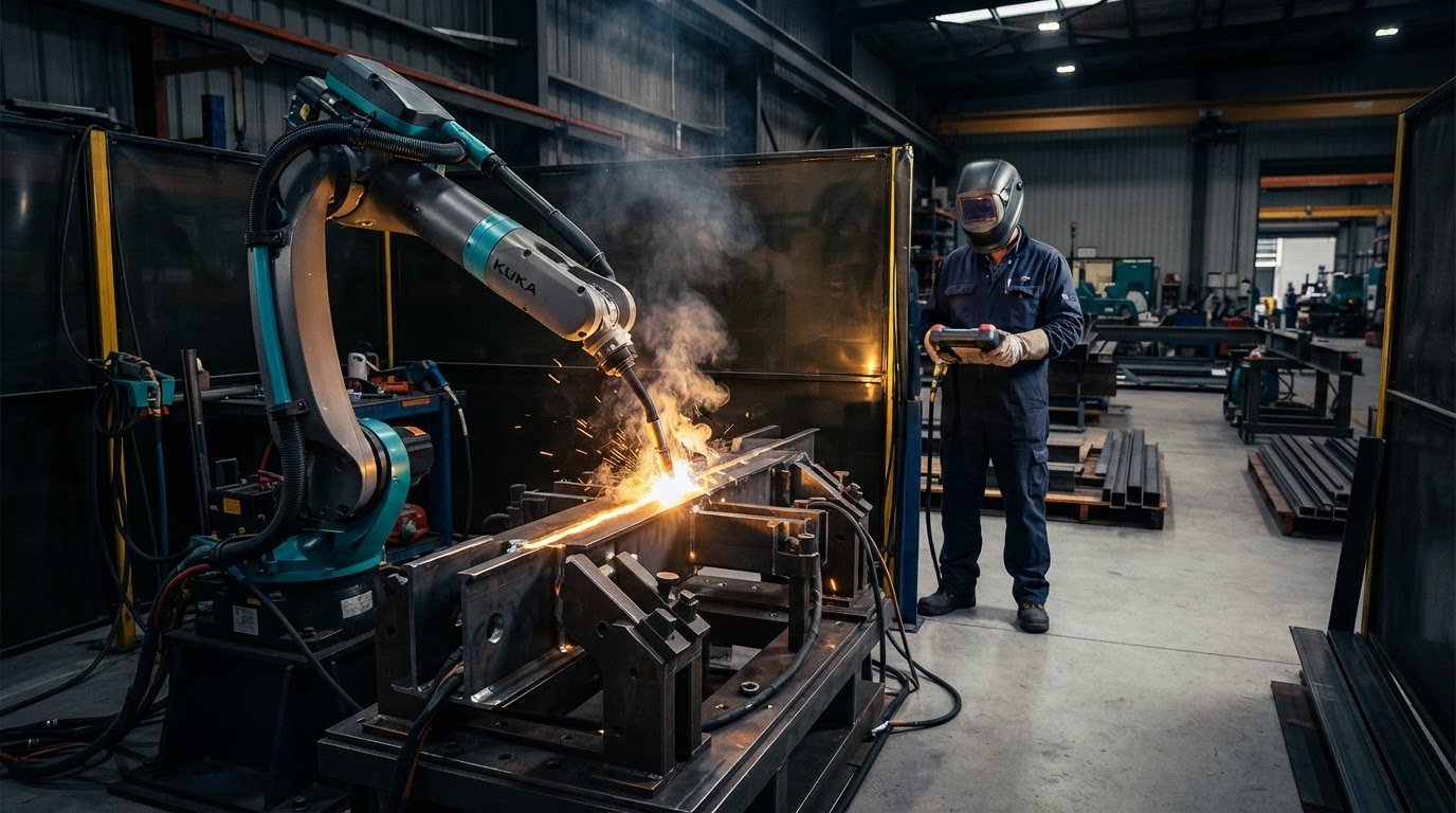
What if a faster weld deposit didn’t produce more finished parts? High deposition rate robotic welding can put more filler metal down in less time, but that figure alone doesn’t show whether a job will move through the workshop faster. Consider weld quality, heat input and rework alongside output. A process that runs quickly can still create delays if parts, fixtures or production flow can’t keep pace.
This guide explains what deposition rate measures, what influences it and where higher output can help. It also covers trade-offs, including how process settings and part requirements affect weld results, so you can compare options against the work you make.
You’ll learn which production conditions may suit automation, what to assess before choosing a robotic welding approach, and why deposition rate matters only when the complete system can use it. For fabricators considering a collaborative robot welding cell, we’ll also cover how no-code teaching, integration and operator onboarding can support a practical assessment while keeping welding expertise central.
Key Takeaways
- Understand what deposition rate measures, and why it isn’t the same as travel speed or finished parts per shift.
- See how wire feed, electrical settings, consumables and joint conditions influence the potential of high deposition rate robotic welding.
- Compare welding approaches by considering joint suitability, access, setup needs and quality controls, not deposition potential alone.
- Use a practical assessment sequence to review part repeatability, batch patterns, fixturing and operator workflow before committing to automation.
- Learn how welding system integration, no-code teaching and operator onboarding can help assess a collaborative robot cell for your production needs.
High deposition rate robotic welding: what the rate measures
Deposition rate is the amount of weld metal deposited over a period of time. It describes how quickly metal is added to a weld, not how quickly a complete component is made. In high deposition rate robotic welding, it helps compare a process’s potential output, but it can’t show on its own how many acceptable parts will leave the workshop.
That distinction matters because a robot is only one part of the welding operation. Part preparation, joint fit-up, positioning, inspection and handling all affect the production result. For a broad overview of robot-based welding and its applications, see Robotic welding.
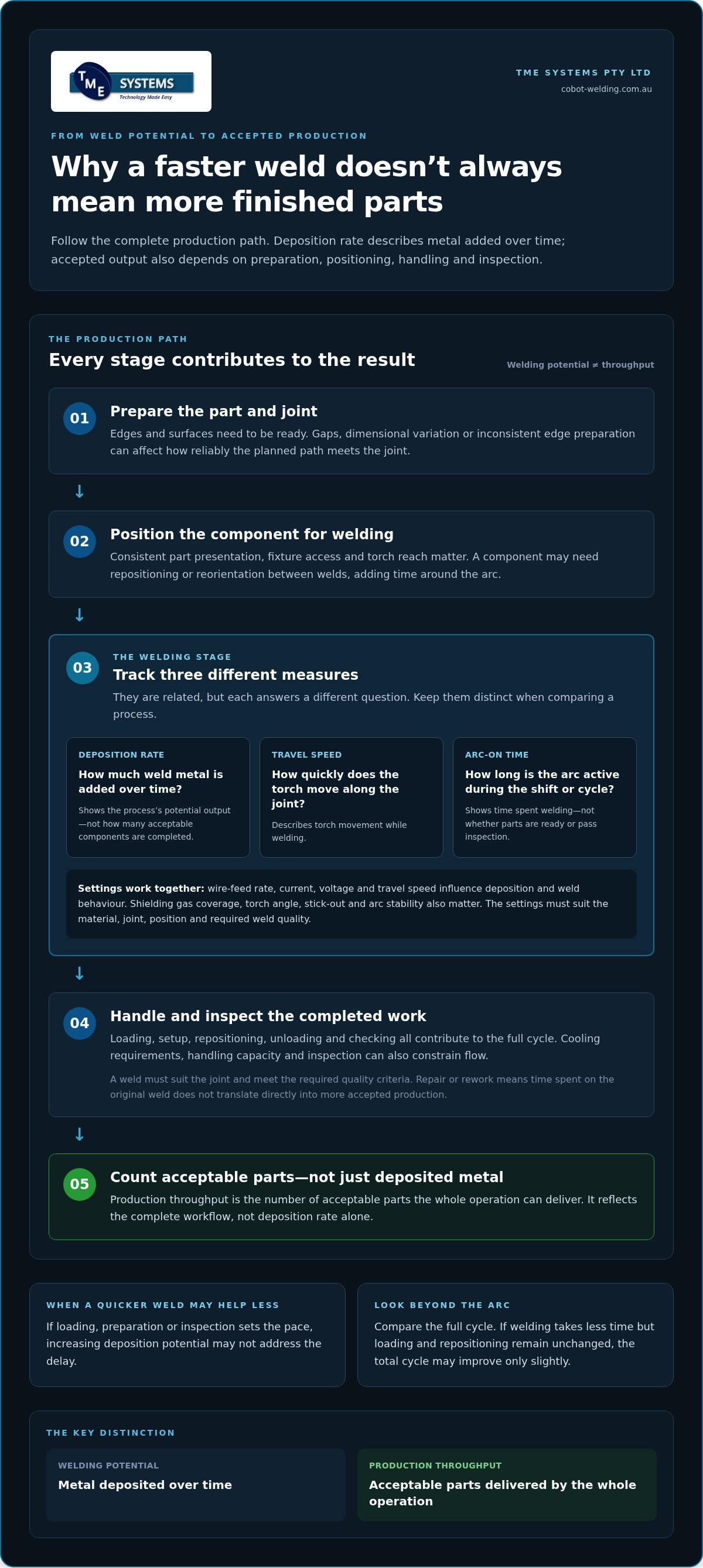
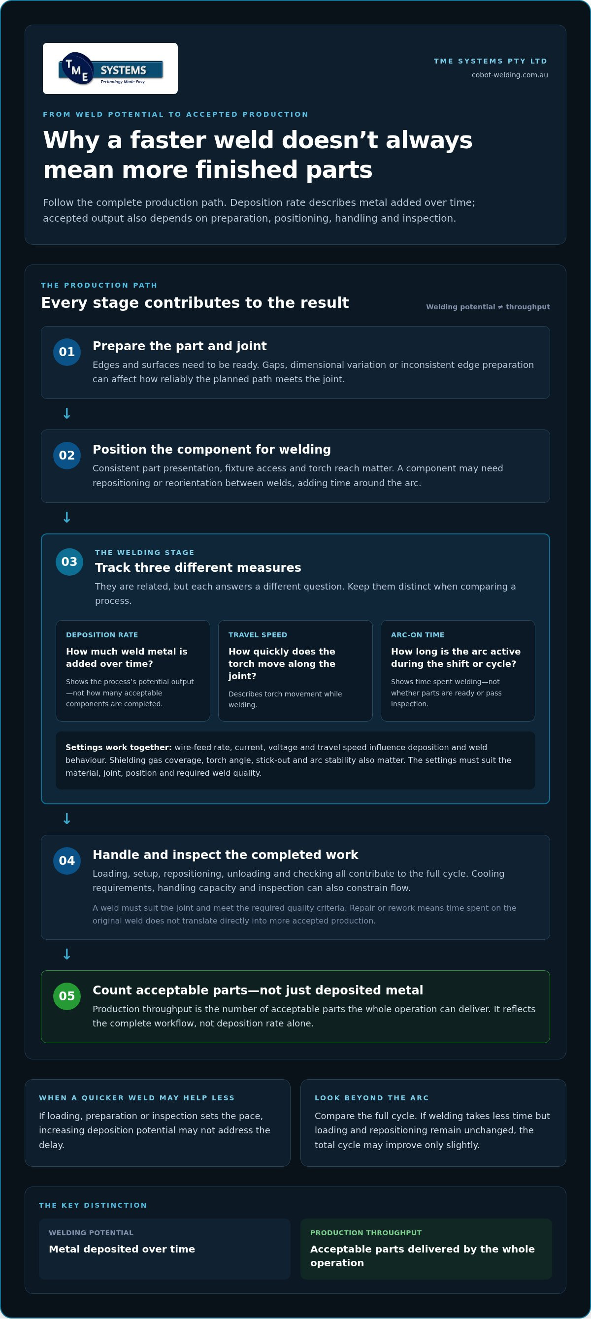
Deposition rate, travel speed, and arc-on time are different measures
Deposition rate describes weld metal added over time. Travel speed is how quickly the torch moves along the joint while welding. Arc-on time records how long the arc is active during a shift or production cycle. These measures are related, but answer different questions: how much metal is deposited, how quickly the weld progresses, and how much available time is spent welding.
Consider a component that is prepared and placed in a fixture before a robot welds it. Deposition rate describes the metal added during welding, while travel speed describes the torch’s movement along each seam. The shift also includes loading, setup, repositioning, unloading and checking the component. A high arc-on share may mean the system spends more time welding, but it doesn’t tell you whether parts are ready to load or will pass inspection.
For a useful comparison, keep the measures separate, then consider them together with the full cycle. If a weld path takes less time but loading and repositioning stay the same, the total cycle may improve only slightly. If preparation or inspection sets the pace, increasing deposition potential may not address the delay.
Why higher deposition does not automatically mean more finished parts
Deposited metal is only one stage in making an accepted component. The weld must suit the joint and meet the required quality criteria. Parts need to be prepared and located consistently, the weld completed, and the finished work inspected. If a result needs repair or rework, the time and resources spent on the original weld don’t translate directly into more accepted production.
Look for constraints around the weld as well as at the arc. Preparation can hold up a job if edges or surfaces aren’t ready. Positioning and access can slow the cycle when a component needs to be moved or reoriented between welds. Cooling requirements, handling capacity and inspection can also limit how quickly completed parts move to the next stage.
Deposition rate is welding potential; production throughput is the number of acceptable parts the whole operation can deliver. Keep throughput in view when assessing whether higher deposition will help your workflow.
What determines deposition potential in robotic welding?
Deposition potential depends on the welding process, consumables and job conditions working together. A robot can repeat a taught path, but it doesn’t remove the need to select settings that produce a stable arc and a sound weld. For high deposition rate robotic welding, the useful question isn’t simply how much wire can be fed. It’s how much weld metal the application can accept while maintaining the required weld quality.
Wire-feed rate, current, voltage and travel speed interact. Wire feed and electrical conditions influence how the wire melts and transfers into the weld, while travel speed affects how the weld is laid along the joint. Raising one setting in isolation can upset the balance. Shielding gas coverage, torch angle, stick-out and arc stability also matter, particularly when working towards higher output. There’s no universal setting for every material, joint or position.
Process variables that influence metal deposition
Wire type and diameter help define the suitable operating range, but their effect depends on the wire, power source and application. Use the consumable manufacturer’s guidance and qualified welding procedures to inform changes. The American Welding Society Welding Handbook is a reference for understanding welding processes and related variables.
Changing feed rate, voltage or travel speed takes more than a quick adjustment at the control. Check that the settings work together, shielding remains effective and the arc behaves consistently. Then assess the resulting weld against the application’s requirements. A qualified welding procedure and suitable weld validation provide the basis for using those settings in production, rather than relying on a promising-looking bead alone.
Part and joint conditions shape the usable rate
The joint determines where the torch must go and the access it needs. Joint geometry, weld length and position can constrain torch angle, approach direction and travel path. A straight, accessible seam presents different demands from a short weld beside an obstruction or a joint that requires the component to be repositioned.
Material and fit-up also influence the process choices available. Gaps, variation in part dimensions or inconsistent edge preparation can affect how reliably the planned path meets the joint. A robot can repeat a taught path, but repeating the same movement won’t correct inconsistent part presentation.
That’s why fixturing matters. A fixture should hold components consistently and present the welds within the robot’s working reach. Consider how the operator loads and unloads parts, locates them, changes between jobs and responds to variation. These details affect whether a welding path can be repeated across a batch.
A test weld is a useful starting point, not proof of production readiness. Validate the application using representative parts, joint fit-up and operating conditions. Review weld quality and repeatability alongside the complete work sequence. A collaborative robot welding cell can form part of that assessment, with cobot welding integration supporting a setup matched to the part and workflow.
Comparing high-deposition welding approaches without overlooking trade-offs
A process with strong deposition potential isn’t automatically the right choice for a production job. Start with the required weld size, joint type and acceptance criteria, then consider which process can meet them reliably within the available access and workflow. GMAW, commonly called MIG welding, and FCAW are two process families to assess, but neither is a universal answer. Suitability depends on the consumables, equipment, joint and qualified welding procedure.
Compare process options against the job
Use the table as a starting point, not a ranking. Actual deposition potential depends on the process setup and operating conditions. Compare options using the same representative parts and joint requirements, then consider how consumable handling, torch access and cell integration affect the production task.
| Process family | Deposition potential | Joint suitability and access | Setup and quality controls |
|---|---|---|---|
| GMAW (MIG) | Can support higher deposition in suitable configurations; confirm against the wire, equipment and procedure. | Assess joint geometry, weld position and whether the torch can maintain the required angle and access. | Manage wire feed and shielding gas. Check arc stability, gas coverage, weld profile and procedure requirements. |
| FCAW | Potential varies with the wire type and process conditions; don’t assume all flux-cored wires behave alike. | Assess the same joint and access constraints, including whether the torch can follow the weld consistently. | Confirm wire and shielding requirements. Include relevant slag management and inspection in the quality plan. |
For either process, integration matters. The system needs to support the selected welding equipment and consumables, while the robot path, torch orientation and fixture must suit the part. A process that looks promising on an accessible joint may be less practical where a component restricts torch approach or requires frequent repositioning.
Include quality and heat input in the comparison
Process changes can alter the balance between electrical settings, travel speed and weld size. Those changes can affect heat input and may influence distortion, depending on the material, joint, restraint and procedure. Avoid treating higher output as a simple matter of increasing a setting. Establish suitable parameters through procedure development, then validate the result against the application’s acceptance requirements.
Quality controls should match the job. Consider how the process will maintain shielding, produce consistent fusion and weld profile, and support inspection. FCAW may involve slag that needs to be managed between passes or before inspection, depending on the application and wire. GMAW relies on suitable shielding and stable arc conditions. Both require checks appropriate to the procedure and finished component.
A deposition comparison is useful only when each process also meets the weld’s quality and acceptance requirements. Compare trial results under representative conditions, including fit-up and position, before settling on a production approach.
A practical checklist for assessing robotic welding suitability
A useful assessment starts with the parts and work sequence, not the robot’s headline capability. Review how consistently components arrive, how often jobs repeat and where time is spent between welds. For a broader introduction to system layout and considerations, see this collaborative robot welding cells guide.
Screen parts, welds, and production conditions
Use this sequence to build a practical picture of the job before deciding whether automation is a fit. Record the actual workflow, including operator tasks and variation between parts.
- Choose candidate parts. Identify components with repeatable welds, recurring production runs or consistent sequences that could benefit from a robot repeating a taught path.
- Map each weld. Note joint type, length, position and torch access. Include seams that require a change in component orientation or a different approach angle.
- Record variation. Check how fit-up, material presentation and weld position vary between parts and batches. Note where operators currently adjust to accommodate those differences.
- Review fixturing. Consider whether parts can be located and held consistently, and whether the fixture gives the torch access to the required welds.
- Map the full workflow. Include upstream preparation and downstream handling, inspection and job changeovers. This helps show whether welding is the constraint or another step sets the pace.
- Consider the people and risk. Define operator tasks, training needs and how the system fits the work area. “Collaborative” doesn’t remove the need to assess the application and its risks. Don’t assume a system is suitable based on its label alone.
Plan a representative trial and measure outcomes
Select components that reflect normal fit-up, material presentation, joint access and production conditions. A straightforward sample can help teach a path, but won’t show how the system handles the variation operators see across a real batch. Treat the trial as a way to identify adjustments and verify process requirements before planning production use.
Agree on what to record before the trial begins. Track accepted welds and rework alongside cycle time, setup changes and the operator’s involvement in loading, positioning, monitoring and job adjustments. Review results across representative parts, not just the best-looking weld. This gives the team a clearer view of repeatability and the work required to keep the cell running.
For wider context on reviewing workflow as well as welding time, apply the same whole-process approach when considering robotic welding productivity improvements. TME Systems supports evaluation through collaborative robot welding cells, system integration and operator onboarding. Explore a collaborative robot welding cell for your workflow.
How TME Systems supports a considered robotic welding evaluation
A sound evaluation connects the part, welding process and production workflow to an appropriate automation approach. TME Systems supplies and integrates collaborative robot welding cells, with no-code teaching software and operator onboarding to support the assessment. The aim isn’t to promise a particular deposition rate. It’s to establish whether the application can be taught, integrated and validated for consistent production.
Connect operator-led teaching with repeatable robotic paths
With no-code teaching software, operators can teach a weld path and make job adjustments through an accessible interface rather than relying on traditional robot programming. This can make it easier to refine a path as the team learns from actual parts and fixtures. The software supports the operator, but doesn’t replace welding knowledge or determine whether a process setting is right for the joint.
Experienced welders remain central. They understand the joint, recognise weld quality issues and help refine how the job is performed. Their input guides path teaching and helps determine whether an adjustment is appropriate within the established procedure. For more detail on this operator-facing approach, explore the no-code robot welding software guide.
That distinction matters for high deposition rate robotic welding: a taught path can support repeatability, but the process and its settings still need to suit the application. Assess the weld result alongside access, part presentation and workflow before treating a trial as evidence of production readiness.
Plan integration, training, and the next step
Integration means considering how the cell fits with existing welding equipment and the way parts move through the factory. Fixtures, operator loading and unloading, job changes and inspection all form part of the practical picture. TME Systems integrates welding systems with existing equipment and workflows, then supports operators through onboarding so they can understand the cell, teach jobs and contribute to ongoing refinement.
Training helps operators work with the teaching interface and the tasks around the welding cycle. It doesn’t remove the need to assess application risks or validate the welding procedure. Keep those checks alongside decisions about cell layout and operator responsibilities.
Once you’ve identified representative parts and what you want to learn from a trial, a mobile welding robot demonstration can help bring the evaluation into a practical setting. To discuss how a collaborative welding cell could fit your parts, process and workflow, talk with TME Systems about your application.
Make your next welding decision with a real job in mind
Turn an automation question into a practical production assessment. Choose a representative part and define what a useful result would look like for your team, from accepted welds to the way operators manage the job. This gives everyone a shared basis for deciding whether high deposition rate robotic welding fits the work, rather than judging a setup by a single process measure.
TME Systems can help you explore the application through no-code weld-path teaching and parameter adjustment, integration with existing welding equipment and workflows, and operator onboarding. A mobile demonstration can also help your team see how the approach relates to its parts and day-to-day tasks. Your welding expertise remains central to refining the process and judging the result.
Bring the production challenge you want to solve, along with the parts and workflow that shape it. Discuss your robotic welding application with TME Systems and take a considered next step towards an approach that works for your operation.
Frequently Asked Questions
What is the difference between deposition rate and travel speed?
Deposition rate measures weld metal added over time; travel speed measures how quickly the torch moves along the joint. They’re related, but changing torch speed alone doesn’t tell you how much metal is deposited or whether the weld meets requirements. For a meaningful comparison, record both measures with the same joint and welding setup. A torch moving faster along a seam isn’t necessarily producing a suitable finished weld.
Does a higher deposition rate always make robotic welding more productive?
No. High deposition rate robotic welding is more productive only if it helps deliver more acceptable work through the full production sequence. For example, a faster weld cycle may have little effect if operators are waiting for parts to be prepared or fixtures to become available. Compare the current method and trial using the same definition of a completed, accepted component, and account for the actual product mix and job changes.
Can high deposition rate robotic welding be used on thin material?
It may suit some thin-material applications, but there’s no general setting or deposition target for every part. Heat input, joint design, material and restraint can affect distortion and weld quality. For example, a test piece may look acceptable before release but shift out of tolerance after welding. Assess the finished component’s dimensions and weld acceptance criteria, and have the procedure and settings technically validated for that application.
Which welding process has the highest deposition rate?
There isn’t one process that ranks highest for every production job. Published or supplier figures can describe particular equipment, consumables and test conditions that differ from your joint and weld position. Compare process options under equivalent conditions and check that each can meet the required weld quality and access needs. Treat a headline rate as a starting point for investigation, not a guarantee of output on your parts.
Does a welding cobot automatically increase deposition rate?
No. A cobot can repeat a taught movement, but it doesn’t set the welding process, consumables or parameters by itself. Those choices determine deposition potential and need to suit the job. TME Systems’ no-code teaching software lets operators teach paths and adjust parameters without traditional programming, while welding expertise remains important for process decisions. Automation may improve path repeatability, but that’s different from an automatic increase in deposition rate.
How should a fabricator measure the results of a high-deposition welding trial?
Use a consistent scorecard for the existing method and trial, and record the parts and conditions used in each. Alongside cycle time and accepted components, note operator interventions, setup adjustments and reasons for rejected welds. Keep the acceptance criteria consistent, and separate time spent welding from time spent preparing or handling parts. This makes it easier to identify what changed and whether the result holds across the planned production mix.