
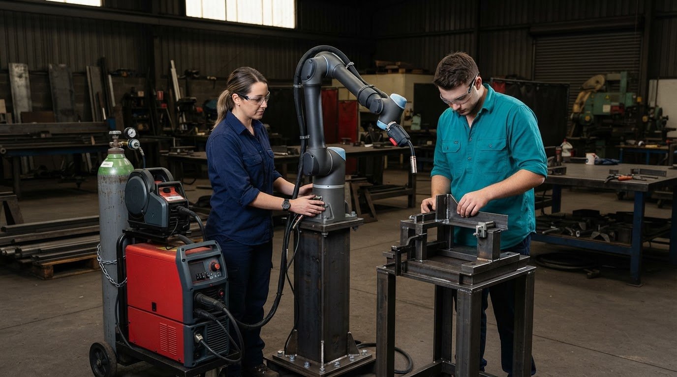
Robotic welding relies on the power source working in step with the wire feed, torch, communication method and weld settings. Good site readiness for robotic welding starts with checking these connections, which affect arc stability and weld repeatability.
A robot may be ready to move, but that does not mean the welding process is ready to produce consistent parts. Equipment, jobs and people on the floor all need to work together, so assess the whole setup before installation.
This guide explains how to prepare your workshop, from power source integration and production requirements to staffing, training and robot configuration. It also covers how to match a cell to your workflow, helping you identify practical gaps before they disrupt production.
Key Takeaways
- Match the power source, wire feed, torch package and weld settings so they work together for stable, repeatable welds.
- Assess whether your parts have consistent fit-up, practical torch access and enough recurring work to justify robotic welding.
- Plan operator training and a robot setup that fits your team’s skills, production mix and safety needs.
- Use welding system integration, no-code teaching software and operator onboarding to connect the cell with your existing workflow.
Why is welding power source integration important?
- Map the full welding system before choosing a robotic weld cell. For MIG/MAG, include the power source, wire feeder, torch and dress package, robot controller and teach pendant. Match the communication method and weld settings to the power source, since incompatible signals or settings can disrupt arc stability and repeatability. Unlike manual welding, robotic readiness also depends on consistent communication and programmed motion. A collaborative robot requires a safety risk assessment for its specific application.
- Confirm that the process and consumables work together. MIG and TIG can both be used when the robot, power source, torch package and process requirements are correctly matched. Choose a robotic MIG gun suited to the application’s duty cycle, with a neck that can reach the joint around the tooling. Consistent wire cast and helix support smooth feeding. For pulsed applications, HDP contact tips can last longer and reduce downtime from tip changes.
- Plan cell equipment around weld quality and maintenance. Secure parts in repeatable positions with suitable fixturing. Include a torch-cleaning or anti-spatter station in the equipment plan. A welding-gun reamer clears spatter from the nozzle and gas diffuser to support shielding-gas flow. A heavy-duty reamer provides more torque and reaches deeper into the nozzle. Multi-feed anti-spatter systems can supply reamers from a drum outside the cell.
- Prepare the site before delivery. Robotic welding systems may require site services and extraction suited to the cell and its application. Have ventilation active and tested, mark floor anchoring points, and clear the planned cable route. In Australia, workplace safety controls should follow a site risk assessment and applicable WHS obligations. Select relevant Australian Standards for the equipment and application through that assessment. Test safety interlocks during every commissioning test; use appropriate barriers, light curtains and operator PPE.
- Set the installation budget according to the project scope. Cost depends on factors such as power-source compatibility, cell equipment, fixturing, site preparation and commissioning. A positioner or dual-station fixture may improve throughput for larger or asymmetric parts, while seam-tracking sensors can help when joint geometry varies. These choices affect integration, so define the parts and weld process before finalising the configuration.
Production workflow and process requirements
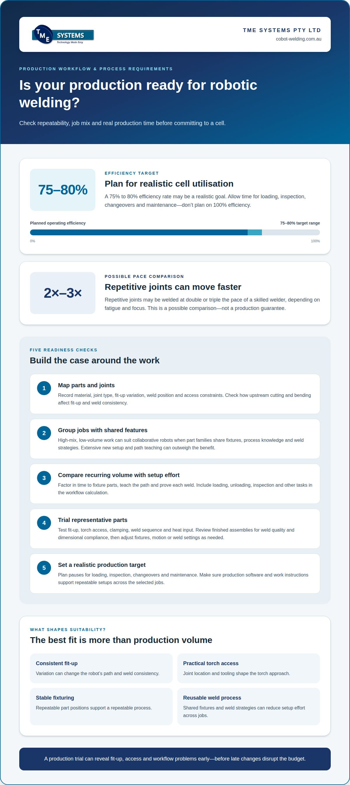
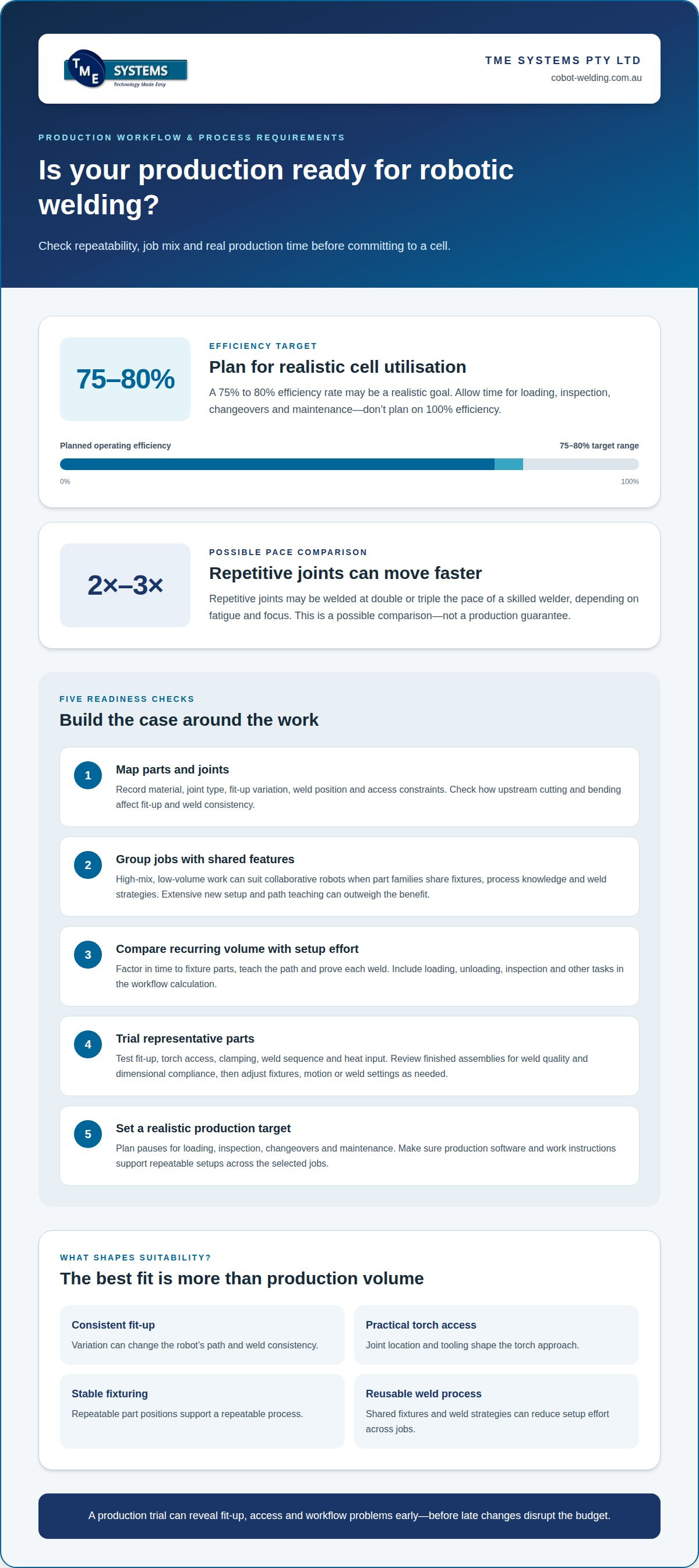
Robot suitability depends on repeatable fit-up, practical torch access, stable fixturing and enough recurring work to justify teaching and proving the weld path. Production volume matters, but joint consistency and the ability to reuse a process also shape the decision.
- Map the parts and joints that could move to robotic welding. Record the material, joint type, fit-up variation, weld position and access constraints. A deep corner joint, for example, may need a different torch approach from an accessible straight seam. Check how upstream cutting and bending affect fit-up, since variation can change the robot’s path and weld consistency.
- Group jobs by the features they share. Collaborative robots can suit high-mix, low-volume production when the right part families are chosen and jobs share fixtures, process knowledge and weld strategies. If every new job requires a different setup and extensive path teaching, the changeover effort can outweigh the benefits.
- Compare recurring volume with the time needed to fixture parts, teach the path and prove each weld. Repetitive joints may be welded at double or triple the pace of a skilled welder, depending on fatigue and focus. Treat this as a possible pace comparison, not a production guarantee. Include loading, unloading, inspection and other tasks in your workflow calculation.
- Run a production trial before committing to full output. Use representative parts to test fit-up, torch access, clamping, weld sequence and heat input. Review finished assemblies for weld quality and dimensional compliance, then adjust fixtures, motion or weld settings as needed. Trials can reveal problems early and help avoid budget overruns caused by late changes.
- Set a realistic efficiency target with planned pauses for loading, inspection, changeovers and maintenance. A 75% to 80% efficiency rate may be a realistic goal for a robotic welding cell; don’t plan on 100% efficiency. Confirm that production software and work instructions support repeatable setups across the selected jobs. For an application review, explore collaborative robot welding.
Staffing, training and robot configuration
- Map who will load parts, teach weld paths, monitor the cell and respond to faults. For each task, identify the skills your welders and operators already have. A welder’s process knowledge can guide joint setup, while an operator’s routine checks help keep production moving. Clarify responsibilities before automation changes the handover between people and equipment.
- Build training around operation and hazard awareness. Operators need to learn the system controls, start-up and shutdown procedures, job changes and fault response. They also need to recognise hazards and know how to avoid them. Use a practical sequence: demonstrate a task, let the operator practise, then check they can complete it safely and consistently.
- Choose a teaching approach that suits the team’s experience. No-code teaching software lets welders and operators teach weld paths without robot-programming experience, using a simpler interface. This helps them apply their knowledge of joint access and sequencing. Allow time to practise editing and saving jobs, not just running an established program.
- Configure the robot around the parts, fixtures and work area. A cell may use a 6-axis articulated arm, but the required reach and access depend on the joint locations and tooling. Plan how the arm approaches each seam without colliding with clamps or the workpiece. Set out the operator’s loading position and movement path alongside the robot’s working envelope.
- Test the handover between the operator and the machine before production. Have an operator load a representative part, select its program, run the weld and complete the required checks. Observe where instructions, controls or fixture changes cause hesitation. Record these points, refine the work sequence and repeat the practice run so every shift can follow the same process.
Integration with existing workflows
- Trace a part’s route from incoming material to finished assembly. Note where cutting, bending, fit-up, welding, inspection and dispatch happen. For example, identify whether welded frames wait between manual welding and inspection. Treat site readiness for robotic welding as a workflow review, not just a check of the cell footprint. This map shows where the cell could sit and how parts would move through production.
- Define the information each application needs at the cell. Gather current weld procedures, job identifiers, fixture details and inspection criteria. Then decide how operators will select the right job and communicate a change. Clear programming and job-selection steps help prevent a correct weld path being run against the wrong part or setup.
- Plan how operators and the production line will work together. Set out how parts arrive, who loads them, where completed assemblies go and how interruptions are handled. In a shared work area, define which tasks remain manual and which move to the robot. This keeps the handover practical and avoids adding an unclear step.
- Reserve space for the cell’s operating needs, not just its footprint. Allow room for part presentation, fixture changes, consumables and routine access. Trace trolley and forklift routes to ensure they do not cross operator positions or block material flow. Check that the cell’s entry and exit points match the direction parts already travel through production.
- Introduce the cell in stages and review the effect on surrounding processes. Start with a suitable recurring job, then assess whether upstream supply, downstream inspection and shift handovers keep pace. As part of site readiness for robotic welding, include how the setup could adapt if workload changes. Modular cells can allow a smaller initial setup to expand with demand. A workflow review can bring together software, equipment, fixtures and production processes. Discuss integrating a welding system with your existing workflow.
TME Systems: Collaborative Robot Welding Cells
TME Systems helps Australian manufacturers assess collaborative robot welding through welding system integration, operator training and onboarding. Turn to TME Systems when you are evaluating how a cell could fit your equipment, production flow and team’s skills.
No-code teaching software is designed for welders and operators without robot-programming experience, helping them teach weld paths using their practical process knowledge. TME Systems’ Mobile Demo System can bring collaborative welding to your workshop for a hands-on evaluation. These options support a considered move from assessing readiness to planning how operators will work with the equipment.
Share the applications you are considering, your existing welding setup and the workflow questions you need to resolve. Contact TME Systems to discuss your robotic welding plans.
Make your next step practical
Use your readiness work to shape a clear first application, not an abstract automation plan. Choose a representative job, define what a successful production run looks like, and involve the people who will operate the equipment. This gives your team a practical basis for deciding how site readiness for robotic welding fits your production priorities.
TME Systems offers collaborative robot welding cells, no-code teaching software and a Mobile Demo System. These support different stages of planning, from exploring collaborative welding to helping operators teach weld paths. The right starting point depends on the job you want to automate and how it fits your existing workflow.
To discuss your application and possible next steps, discuss your project with TME Systems. A clear first job can make the path from assessment to adoption easier to work through.
Frequently Asked Questions
What does a site need to be ready for robotic welding?
A site needs compatible welding equipment, suitable utilities, a workable cell layout, safe operator access and parts that can be presented consistently. Plan how each job moves from storage to the fixture and on to inspection. Allow for consumables, maintenance access and clear operator instructions. Readiness means the equipment and production routine work together, not simply that the robot fits on the floor.
What are the floor space, layout and foundation requirements for a robotic welding cell?
Space and foundation requirements depend on the robot’s reach, workpiece dimensions, fixtures, loading method and cell safeguards. Map the robot’s motion alongside the operator’s loading position, material-handling routes and servicing access. Mark the intended anchoring points before delivery and keep cable routes clear. A large or awkward assembly may need a different layout from a compact repeat part, even if both use similar welding equipment.
What power supply, compressed air and ventilation are required for robotic welding in Australia?
Match the electrical supply to the selected welding power source and cell equipment, and provide compressed air and shielding gas where the process requires them. Fume extraction should suit the welding task and be operating before welding begins. In an Australian workshop, plan controls around the hazards identified in the site risk assessment, including fume exposure, arc radiation and access to moving equipment. Operators still need appropriate personal protective equipment.
What are the steps and lead times for preparing a site for robotic welding?
Prepare in sequence: define the parts and welding process, map the cell layout, plan utilities and extraction, prepare anchoring and cable routes, then install and test the equipment. Lead time depends on how much site work, equipment integration, fixture preparation and production validation the project needs. For example, a cell needing a new layout and utility changes involves different preparation from one fitting an existing production area.
What are the main risks of installing a robotic welding cell in an existing workshop?
Common risks include obstructed material routes, insufficient access for loading or maintenance, inconsistent part fit-up, and utilities or extraction that do not suit the application. Poorly planned interaction between operators and robot motion can also create hazards. Assess the actual tooling, process and work area, then test safeguards and interlocks during commissioning. A staged production trial can reveal workflow conflicts before the cell becomes part of routine output.