
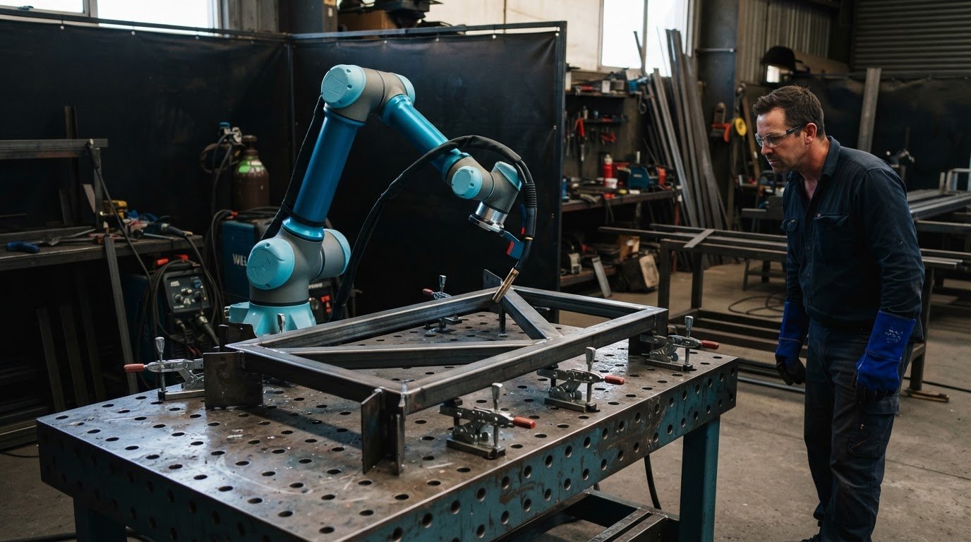
A weld path that looks sound on screen can still disrupt production if the robot cannot reach a joint or clear a fixture. Verifying weld paths before production means checking the planned route against the physical cell, including weld identifiers, reach, collision clearance and joint limits. Finding issues early gives the team time to adjust the path before the production run.
Downtime involves more than a paused robot. Operators may need to diagnose the issue, reset the cell and refine the path while other work waits. A structured pre-production check focuses attention on details likely to disrupt the run and keeps the operator’s practical knowledge central.
This guide covers checking the cell setup, confirming each weld and identifier, testing reach and clearance, and refining paths around joint limits. It also explains how to make these checks repeatable, so the team can identify and address potential problems before production begins.
Key Takeaways
- Use pre-weld checks to spot surface preparation and joint issues before they create inspection bottlenecks.
- Test the robot’s reach, clearances and joint movement across the full path, not just at the start and finish.
- Refine weld routes and identifiers against the part and fixture setup so instructions are clear on the production floor.
- Match simulation software to the physical cell, with accurate calibration of the TCP, reference frames and fixture positions.
Reducing inspection queues and detecting defects earlier
Use staged inspections to spot visible defects early and flag welds that need further examination. Compare torch angle, travel speed and weld position with the approved procedure and joint geometry. Skipping this check can leave alignment problems undiscovered until repair or reinspection interrupts production.
-
Check torch angle, travel speed and position
Run a controlled path check and compare the torch angle, travel speed and weld position with the procedure and the actual joint. Confirm that the torch follows the intended line from start to finish, including changes in direction. A path that appears aligned at the start may drift near a fixture or joint edge, so assess the whole route before releasing the weld for production.
-
Inspect for safety and performance
Examine joint fit-up, surface preparation and weld appearance before deciding whether further inspection is needed. Visual inspection gives an initial quality check, but it cannot identify every weld issue. Use welding gauges to compare weld size, leg length and reinforcement height with the job specifications. For visual inspection, BS EN ISO 17637 sets minimum illumination at 350 lux and recommends at least 500 lux.
- Record each inspection and non-destructive examination result against its weld identifier. Note the findings, acceptance decision, and any repair or reinspection status so the production team can distinguish released work from items awaiting review. Linking records clearly to the weld map helps prevent inspection queues from becoming production bottlenecks.
- Consider in-process imaging when the application calls for additional visibility. SpaceX mounted an X-ray inspection harness on a welding robot to inspect welds during welding. This example shows how inspection can be integrated into the process. Visual checks and gauges also provide practical ways to assess appearance, dimensions and alignment before production proceeds.
Checking reachability, collisions and joint limits
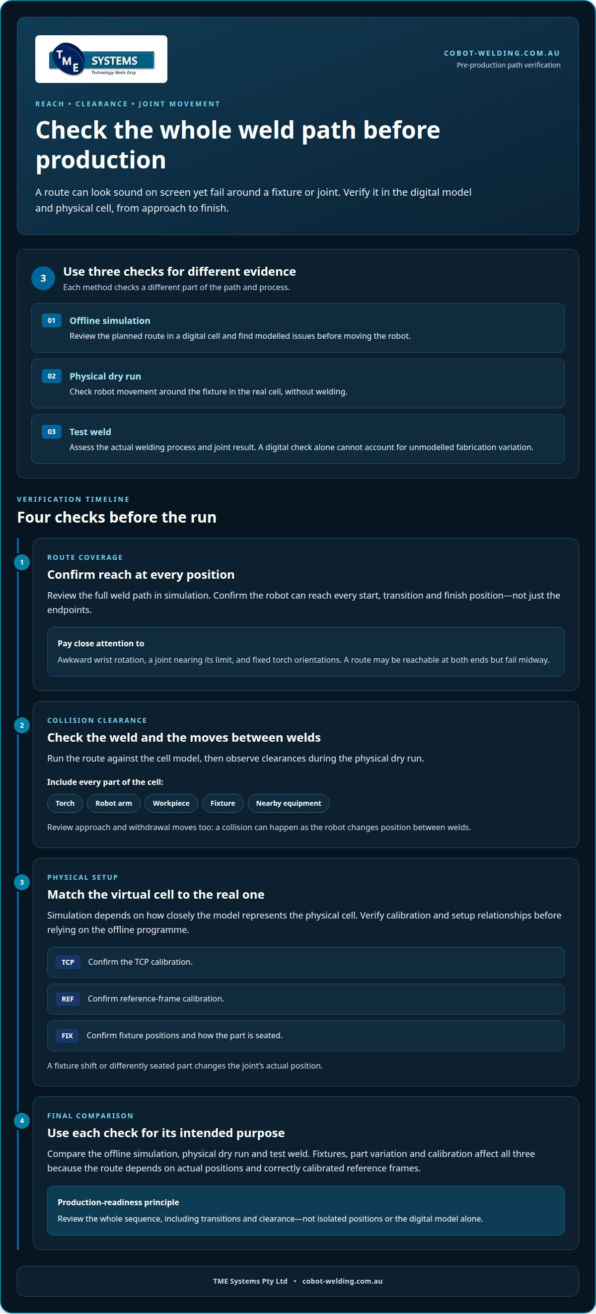
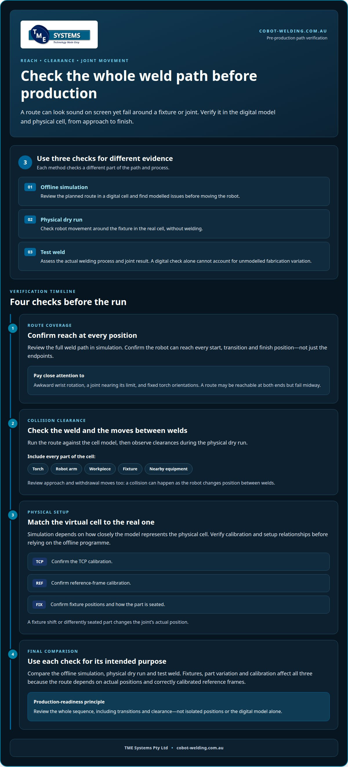
Verifying weld paths before production combines digital review with checks in the physical cell. Compare offline simulation, a dry run and a test weld: simulation reviews a digital cell, a dry run checks robot movement in the physical setup, and a test weld assesses the welding result. Fixtures, part variation and calibration affect all three because the path depends on actual positions and correctly calibrated reference frames.
-
Compare simulation, dry runs and test welds
Start with offline simulation to review the planned route and identify issues in the model before moving the robot. Then run a dry cycle in the physical cell, checking the torch’s movement around the fixture without welding. A test weld provides evidence about the actual process and joint result. Use each method for its intended purpose: a digital check alone cannot account for unmodelled fabrication variation.
-
Check reachability and joint limits
Review the full weld path in simulation and confirm the robot can reach every start, transition and finish position. Watch for awkward wrist rotation or a joint nearing its limit, especially where the torch must approach from a fixed orientation. A route may be reachable at both ends but fail midway, so check the whole sequence rather than isolated positions.
-
Check for collisions
Run the path against the cell model, including the torch, robot arm, workpiece, fixture and nearby equipment. Review approach and withdrawal moves as well as the weld itself, since a collision can occur between welds as the robot changes position. During the physical dry run, observe the same clearances and adjust any route that brings equipment too close.
-
Account for fixtures, part variation and calibration
Match the virtual cell to the physical setup before relying on simulation. Offline program accuracy depends on correct TCP, reference-frame and fixture-position calibration, and on how closely the model represents the real cell. A fixture shift or differently seated part changes the joint’s actual position. For collaborative robot welding cells, include those setup relationships when verifying weld paths before production.
Creating and adjusting weld paths
Build the route around the joint, then refine its sequence and welding parameters against the approved procedure. A useful path links the drawing, weld identifier and actual part, keeping adjustments clear during production and inspection.
- Start with the joint geometry and weld identifier on the fabrication drawing. Define how the torch approaches, starts, travels and exits, including transitions between welds. For a structural assembly, map each route to its joint and orientation before creating the robot motion.
- Set the path’s welding parameters according to the applicable Welding Procedure Specification. Record the relevant pass sequence, filler metal and amperage, and make sure the program uses the procedure’s parameter format. A path that follows the joint but uses mismatched settings is not ready for production.
- Shape the route to follow the joint profile rather than forcing a straight line across changing geometry. At a corner or curved section, use controlled points to keep the torch travelling along the intended seam. Avoid unnecessary waypoints, which can complicate adjustments and make the route harder to read.
- Adjust the path using a test weld and its examination results. A draft procedure is tested by making a weld to it and subjecting the weld to non-destructive and mechanical testing. If the results call for changes, revise the route or settings, then retain the updated values and outcomes in the procedure qualification record.
- Keep each change traceable. A PQR records the actual values used and test outcomes when qualification testing meets the code’s acceptance criteria. Link the record to the weld identifier and program revision so operators can distinguish the current path from an earlier version or superseded parameter set.
- Review whether the path supports the required quality level before release. For structural steelwork, AS/NZS 1554 covers general fabrication and structures subject to fatigue loading. Keep the approved procedure, path revision and inspection records aligned, so a change to the route does not leave production working from conflicting instructions.
What equipment and software are used to simulate and validate weld paths?
Use offline simulation software alongside the physical welding cell to assess a program before production. Accuracy depends on how closely the virtual cell matches the real setup, including its robot, tooling and fixtures. These steps help make the software review and equipment checks useful on the workshop floor.
- Load the robot, workpiece and fixture layout into the offline simulation environment. Compare each model with the physical cell, since a missing clamp or misplaced fixture can make the simulated route misleading. Keep the part and tooling arrangement consistent between the model and production setup.
- Set the robot’s tool centre point (TCP) and reference frames according to the actual cell setup. These values define how the software interprets torch position and workpiece coordinates. Incorrect calibration can shift the simulated path away from the intended joint, even when the route appears aligned on screen.
- Use simulation to review the weld sequence, torch approach and movement between joints. Check the route against the fixture and surrounding cell geometry, then revise any path based on an inaccurate model. Simulation helps assess planned movement, but it cannot correct inaccurate input data.
- Transfer the reviewed program to the physical cell and compare its movement with the simulated route. Run a controlled dry cycle so the operator can observe the torch, robot and fixture together. Differences between the virtual model and the actual setup can reveal calibration or layout details that need adjustment.
- Record the model version, calibration values and program changes alongside the relevant weld identifiers. If a fixture moves or the part setup changes, update the simulation inputs before relying on the existing path. This keeps the software review connected to the production cell’s actual configuration.
For a practical way to teach and refine paths, explore no-code weld path teaching software.
TME Systems
TME Systems Pty Ltd helps manufacturers make pre-production path checks part of a practical collaborative welding workflow. Its no-code teaching software lets operators teach weld paths and adjust parameters without writing code, keeping hands-on experience central. TME Systems Pty Ltd also offers collaborative robot welding cells and integration to help businesses plan a new setup or fit a cell into existing production.
To assess the approach before making decisions, the Mobile Demo System brings a welding cell to your site for a demonstration. The right next step depends on your parts, fixtures, weld requirements and production process. Discussing these details helps shape an approach around the work, rather than forcing the work to fit a generic path.
Contact TME Systems Pty Ltd to discuss your weld path verification needs.
Make path validation part of every production change
Build weld-path validation into your production change process rather than treating approval as a one-off event. A revised part, fixture or welding procedure can affect how an approved route performs. Set a clear trigger for reviewing the affected program, and involve operators so their practical experience informs each adjustment.
This makes verifying weld paths before production an ongoing part of preparing work, not a task added after a problem appears. It also helps keep program revisions aligned with how jobs actually move through the cell. Start with changes most likely to affect the route, then establish a repeatable review process that fits your production workflow.
If you’re planning that next step, discuss weld path verification with TME Systems. A considered process can help your team approach welding automation with confidence and keep skilled operators central to the work.
Frequently Asked Questions
Does this help reduce downtime in welding production?
Yes. Reviewing a weld route before a scheduled production run can reveal adjustments while the cell is available for preparation. For example, if a joint requires an awkward torch approach, the team can address it before the job enters the production queue. The benefit depends on finding the issue early enough to revise the path, setup or work sequence before the run.
How accurate is offline programming for welding?
Offline programming can represent planned robot movement accurately when the virtual cell reflects the physical setup. It is less useful when the model does not match the robot, torch, workpiece or fixture. For example, simulating a revised component requires the revised geometry, not an earlier part model. Treat simulation as a planning tool, then assess the program in the production cell.
What Is a Weld Map?
A weld map is a drawing or digital record that identifies weld locations and connects them with relevant production and inspection information. On a complex fabrication, it helps the team find which joint a record refers to, rather than relying on memory or vague location descriptions. ISO 3834-2 Clause 7 requires weld-level traceability; a weld map is a standard method for managing it on complex fabrications.
What is weld path verification before production?
It is a review of the robot’s planned weld movement and setup before production starts. The aim is to confirm that the path matches the intended joint and can be carried out in the cell. For example, checking a new part family includes confirming that its weld locations and approach directions are represented correctly in the robot instructions.
How do you verify a robotic welding path before production?
Review the part and weld sequence, then assess the planned route in the context of the cell. Confirm the intended torch approach and movement, and check that the workpiece and fixtures match the setup represented in the program. Follow with a controlled physical run and have the operator observe the movement. Record adjustments against the relevant job or weld identifier.
What are the steps for checking weld path accuracy and reachability?
First, match the program to the correct part and weld locations. Then review the complete route, including transitions between welds, and confirm the robot can reach each required position. Check clearance around fixtures and other cell equipment. Compare the planned movement with a controlled run in the physical setup, then document corrections before releasing the revised path.