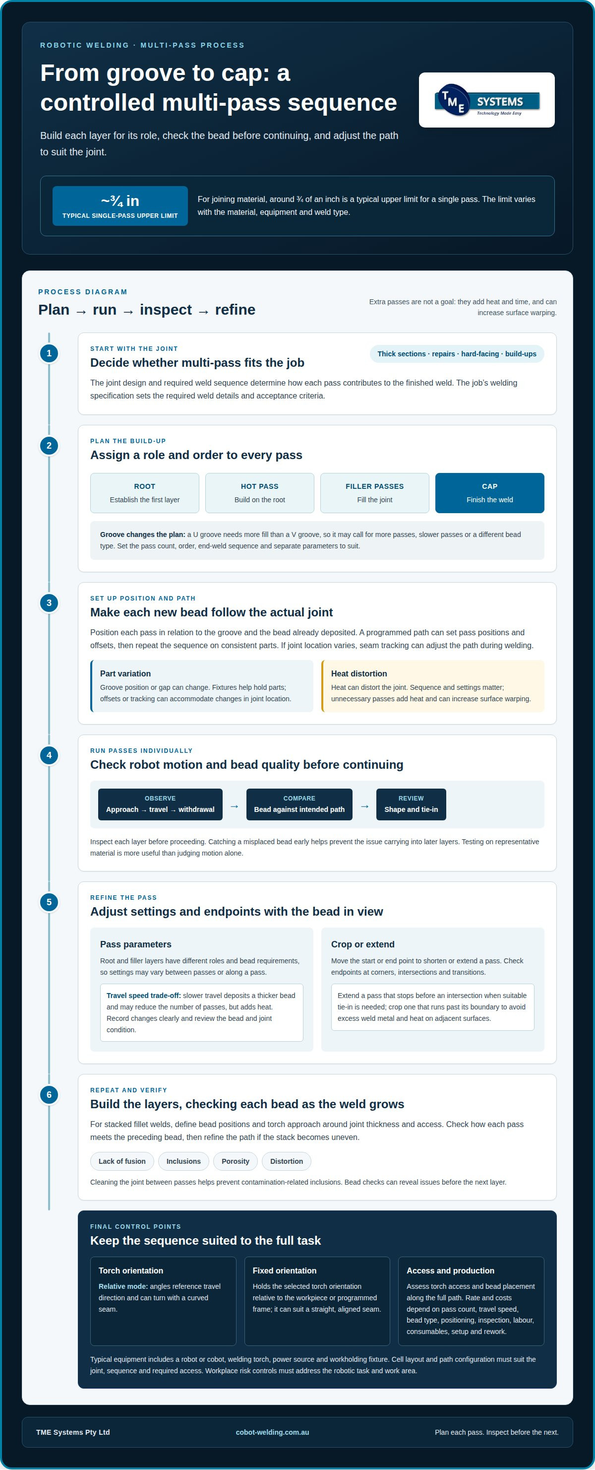

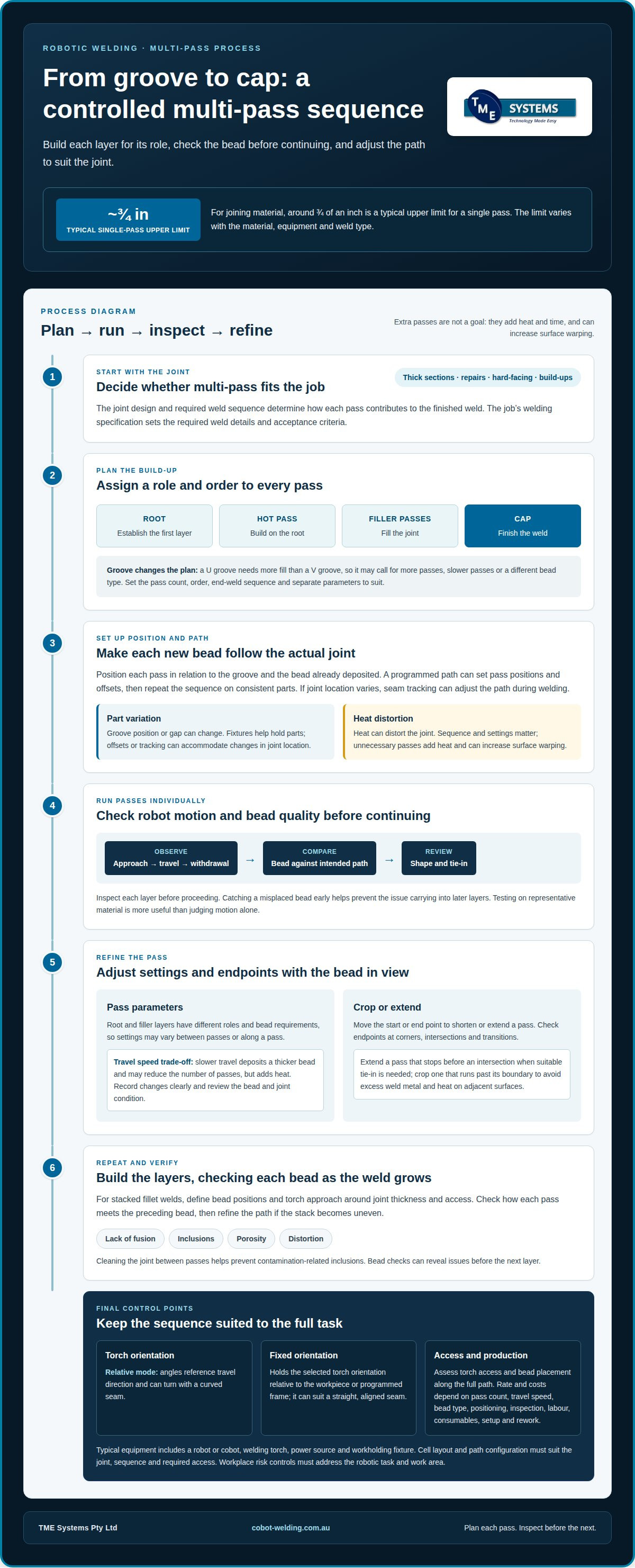
A thick joint doesn’t automatically need the same welding approach from root to cap. Multi-pass robotic welding techniques are used for thick sections, repairs, hard-facing and build-ups; around 3/4ths of an inch is a typical upper limit for joining material in a single pass, though the limit varies with the material, equipment and weld type.
Adding passes is not a goal in itself. Each pass should suit the joint and build on the weld beneath it, from the root and hot passes through the filler layers to the cap. Unnecessary passes add heat and time, and can increase the risk of surface warping.
This article explains when multi-pass welding is needed, what determines the number and pattern of passes, and how to assess robot motion and weld quality as each pass is made. It also explains how travel and work angle modes apply to cobots, so you can see how they fit into a controlled welding process.
Key Takeaways
- Plan the pass layout around the groove and weld sequence so each layer has a clear role.
- Assess robot motion and bead quality after each pass to catch issues before they carry into later layers.
- Choose relative or fixed travel and work angle modes to suit the joint geometry and torch orientation.
- Use cobot path teaching and parameter adjustment to make multi-layer welding more manageable for operators.
When is Multipass Welding Needed?
Multi-pass welding suits thick sections, repairs, hard-facing and material build-up. Joint design and the required weld sequence determine how each pass contributes to the finished weld.
Tracking Subsequent Weld Passes
Tracking successive weld passes means positioning each new pass in relation to the groove and the bead already deposited. This alignment matters: an offset can leave parts of the joint unfilled or distribute weld metal unevenly.
A programmed path can set the position and offset for each pass, then repeat the sequence on consistent parts. If joint location varies, seam tracking can adjust the path during welding, helping later passes follow the actual groove rather than relying only on nominal part dimensions.
Multipass Construction and Applications
A multi-pass weld builds the joint through a root pass, hot pass, filler passes and a final cap pass. This sequence is used to join thick material, repair worn areas, build up surfaces or apply hard-facing.
Pass count and bead layout depend on the groove and the material to be deposited. A U groove needs more fill than a V groove, so it may call for more passes, slower passes or a different bead type. A path layout can assign the number and order of passes, including end weld sequences, and set separate welding parameters for each pass.
Managing Part Variation and Distortion
Part variation can change the groove position or gap, while welding heat can distort the joint. Both affect whether the next pass lands consistently and whether the finished weld has the intended shape.
Fixtures help hold parts in position, while path offsets or tracking can accommodate changes in joint location. The sequence and settings matter too: unnecessary extra passes add heat and can increase surface warping. Inspect each layer before continuing to catch a misplaced bead before it affects subsequent passes.
Production rate depends on pass count, travel speed, bead type, and the time spent positioning or inspecting parts. Costs also depend on labour, consumables, setup, rework and the time needed to complete the specified weld.
In Australia, the job’s welding specification sets the required weld details and acceptance criteria. Workplace risk controls must also address the robotic task and work area.
Common defects include lack of fusion, inclusions, porosity and distortion. Cleaning the joint between passes helps prevent contamination-related inclusions, while checking each bead can reveal issues before the next layer.
Typical equipment includes a robot or cobot, welding torch, power source and workholding fixture. The cell layout and path configuration must suit the joint, pass sequence and required access.
Executing individual passes to check robot motion and welding
Running passes individually lets the operator assess the robot’s motion and the deposited bead before running the full sequence. It can also reveal where travel, settings or pass boundaries need adjustment.
First, observe the torch’s approach, travel along the joint and withdrawal at the end of a pass. Compare the bead with the intended path, then review its shape and tie-in before proceeding. This helps catch motion or weld issues early, before they carry into later layers. Testing on representative material is more useful than judging motion alone.
Adjusting Pass Parameters
Pass parameters are the welding settings assigned to each stage, adjusted between passes or along a pass. Separate settings matter because root and filler layers have different roles and bead requirements.
Travel speed affects bead deposition and heat input. Slower travel deposits a thicker bead and may reduce the number of passes, but adds heat. Review the bead and joint condition before changing settings. Record each change clearly so the operator can connect the result to the specific pass and sequence.
Cropping and Extending Passes
Cropping shortens a pass by moving its start or end point; extending it carries the weld further along the joint. Accurate endpoints matter at corners, intersections and transitions, where stopping too early can leave an incomplete area.
For example, a pass that ends before a joint intersection may need extending to achieve a suitable tie-in. If it runs past the intended boundary, cropping can prevent excess weld metal and heat on adjacent surfaces. Review the revised endpoint against the part geometry before running the sequence again.
Stacking Fillet Weld Passes
Stacking fillet weld passes means placing successive beads to build the required weld profile across the joint. Planning their order helps each bead support the next and reduces the risk of leaving an unfilled area.
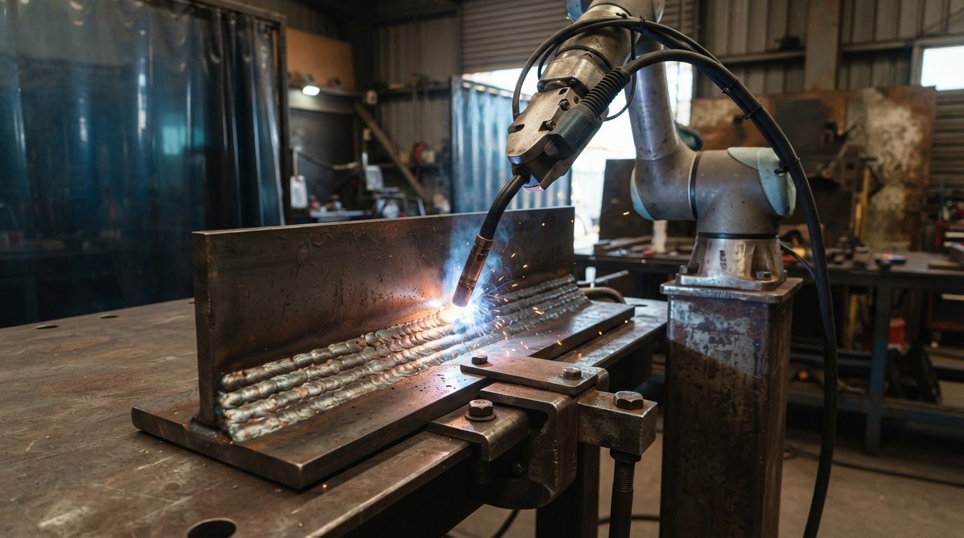
For a larger fillet, define the bead positions and torch approach around the joint’s thickness and access. Check how each pass meets the preceding bead, then refine the path if the stack becomes uneven. A robotic welding system can be configured around these pass sequences, with operator review guiding adjustments before production.
Relative and fixed travel and work angle modes
Travel and work angle modes define how the torch is oriented to the joint as the robot moves. Choosing the right method helps maintain bead placement when a seam changes direction or position.
In relative mode, torch angles are referenced to the direction of travel. As the robot follows a curved seam, its orientation can turn with the path while maintaining the programmed relationship between torch and joint. This can suit a changing seam where the torch approach needs to follow the local direction.
Fixed mode holds the selected torch orientation relative to the workpiece or programmed frame. It can suit a straight seam where the joint stays aligned and the torch needs to maintain a consistent position. At a corner or on a changing surface, however, the same fixed angle may no longer provide the right approach. Assess torch access and bead placement along the full path.
Travel speed also affects the result. Slower travel deposits a thicker bead and may mean fewer passes, but it adds heat to the joint. Choose a speed that balances bead geometry, heat input and the required weld sequence.
Bead type also influences the choice. Stringer beads are thinner and faster but require more passes; weave beads deposit more material and may need fewer passes. For example, a narrow groove may suit stringer beads, while a wider groove may call for a planned weave. Either method must maintain suitable positioning across the joint.
Seam tracking can refine torch position as the cobot follows a joint. Seam tracking can help adjust the torch path during welding to account for joint variation. It can address variation that a fixed path cannot follow, but does not replace selecting suitable angles and travel settings for the weld.
For a practical comparison, assess relative and fixed modes on the same representative joint. Review bead shape and torch access along straight sections and transitions, then adjust the method where the seam’s position or direction changes.
Multi-pass cobot welding
A cobot can support multi-pass robotic welding techniques when a workshop wants to automate suitable repeat work while keeping operators involved. The key question is whether the part family and welding process suit a repeatable task, not whether every job should be automated.
High-mix, low-volume work can be automated when the right part families are chosen. Parts with repeat demand and a practical welding sequence are better candidates than jobs that change substantially from piece to piece. This focuses engineering effort on tasks where a collaborative cell can be put to meaningful use.
The weld process must also match the cell’s robot, power source and torch package. MIG and TIG can both be used when those elements meet the process requirements. Integrating the cell with existing welding equipment and production processes helps make the setup work in the workshop.
Pass quality still depends on sound weld preparation and procedure. In the described multipass sequence, the root pass is intended to achieve 100% penetration through the workpieces. Later weld metal builds on that foundation, so an issue at the root affects the layers above it. Cobot automation supports repeatable motion, but it doesn’t replace the need for a suitable welding procedure or skilled oversight.
Collaborative operation requires attention to the specific application. Safety requirements depend on the tooling, welding process and site risk assessment, and the cell’s working arrangement must account for those factors. They help determine whether multi-pass robotic welding techniques suit the task and production environment.
For a practical discussion about whether your welding application is a good fit, discuss cobot welding for your workpieces.
TME Systems: Collaborative Robot Welding Cells
TME Systems Pty Ltd helps Australian manufacturers apply robotic welding to repeatable tasks, including multi-pass work on thick joints. Its collaborative robot welding solutions pair cobot welding with No-Code Teaching Software, so operators can teach weld paths and adjust parameters without traditional programming.
When your team is assessing a new weld sequence or considering how a cobot could fit into production, TME Systems Pty Ltd’s integration services connect the welding process with the cell setup. Its Mobile Demo System can bring the technology to your workshop for hands-on evaluation. These options suit manufacturers looking to build on operator skill while refining how welding tasks are taught and repeated.
To discuss collaborative robot welding for your application, contact TME Systems Pty Ltd.
Plan the next step for your weld cell
Use your next planning discussion to connect the joint design with the realities of your production floor. A part drawing, sample component and current weld sequence can help identify where a cobot may fit, what operators need to teach, and how the process should be integrated. Choosing multi-pass robotic welding techniques is not just a path-planning decision; it also means involving operator experience in refining the task.
TME Systems offers No-Code Teaching Software and collaborative robot welding solutions to support operator-led path teaching and parameter adjustment. Its Mobile Demo System provides a hands-on way to explore how collaborative welding could suit your parts and workflow. These offerings can turn a broad automation idea into a practical discussion about your specific welding task.
Contact TME Systems to discuss welding and consider how a cobot could support your next production step. Your team can build from its existing welding knowledge and move forward with a clear, considered plan.
Frequently Asked Questions
What is multi-pass robotic welding and when is it used?
Multi-pass robotic welding deposits weld metal across a joint in successive passes rather than one continuous weld. It is used when the joint’s thickness or groove volume calls for layered fill, and for applications such as repairs or material build-up. The project’s welding specification may also require a multi-pass weld. The sequence must suit the joint and the required finished profile.
Which welding processes and joint types suit multi-pass robotic welding?
MIG and TIG can both suit robotic multi-pass work when the robot, power source, torch package and process requirements are correctly matched. Groove joints, including V- and U-grooves, and fillet welds can use multiple passes. Joint shape, fit-up and torch access affect the path and bead arrangement. Parts with repeatable fit-up and stable fixturing can make a practical automation candidate.
How do you program robot paths and sequence passes for multi-pass welding?
Define a path for each layer, then arrange the paths in the required welding sequence. The layout can specify torch position and orientation, oscillation movement, pass count and separate settings. Operators can teach and adjust weld paths using no-code teaching software, without writing traditional robot code. For changing jobs, keeping each pass separately adjustable helps refine one part of the sequence without rebuilding every path.
How are interpass temperature, heat input, and cooling controlled?
Manage heat through pass settings, travel speed and planned pauses between layers. Slower travel deposits a thicker bead but adds heat; allowing the joint to cool before the next pass can help manage heat-sensitive work. The appropriate interpass temperature depends on the material and welding procedure, so follow the job’s specified limits rather than applying one temperature to every joint.
What wire, shielding gas, and welding parameters are recommended for each pass?
No single wire, gas or parameter set suits every pass. Selection depends on the base material, welding process, joint design and applicable welding procedure. For MIG, match wire and shielding gas to those requirements; TIG uses a different consumable and shielding arrangement. Set parameters for each pass’s role, then assess the resulting bead before applying those settings to the rest of the sequence.
How do robotic multi-pass welding systems handle seam tracking and weld inspection?
Seam tracking can adjust the torch path to follow the joint rather than relying only on its programmed position. Through-the-arc tracking can correct contact-tip-to-work distance and steer a cobot towards the centre of symmetrical joints. Inspection still matters: examine each completed bead for profile and continuity before covering it with another layer. This gives the operator a chance to address visible issues while they are still accessible.