
What if a welding arc could transfer metal in controlled bursts rather than running at one steady current? That’s the idea behind pulse MIG, but waveform terminology can make its workshop benefits hard to judge. This guide gets robotic pulse MIG welding explained in practical terms: current cycles between a higher peak and a lower background level, helping control droplet transfer and manage average heat input.
If you’re weighing pulse against another transfer mode, the choice isn’t automatic. A pulsed process may suit some thinner materials or weld positions, but results depend on the material, joint fit-up, torch access and power-source waveform. Selecting a pulse programme alone won’t make a robotic weld consistent.
Here, you’ll learn how the pulse cycle affects metal transfer and heat, where it may offer a practical advantage, and why application trials matter. We’ll also cover the process settings, joint access and operator-led path adjustments to assess before automation. For Australian manufacturers, collaborative robot welding cells and no-code teaching software can support that evaluation, while integration and operator onboarding help put the process into practice.
Key Takeaways
- Get robotic pulse MIG welding explained in plain English, including how the welding process differs from the robot’s torch movement.
- Learn what the pulse waveform changes during metal transfer, and why the selected programme matters.
- Compare pulsed MIG with short-circuit and spray transfer to identify practical trade-offs for a particular weld.
- Assess joint access, fit-up, material, welding position and cycle requirements before choosing a transfer mode.
- Use a structured trial with representative parts and documented inspection criteria to judge whether pulse suits the job.
What robotic pulse MIG welding is, and what pulsing changes
Robotic pulse MIG welding combines gas metal arc welding with a pulsed current and a robot that guides the torch. The technical term for the welding process is gas metal arc welding with pulsed-spray transfer, or GMAW-P. A continuously fed wire electrode melts to form the weld, while shielding gas protects the arc and weld pool.
Pulse MIG is a way of controlling metal transfer in a welding arc, not a robot-specific welding process. The power source manages the arc and current; the robot follows a taught path and positions the torch. That distinction matters: an appropriate pulse programme can’t compensate for a torch that can’t reach the joint or a part that hasn’t been prepared consistently.
For more background on the process, the Gas Metal Arc Welding (GMAW) with pulsed-spray transfer overview describes how pulsed-spray fits within the wider GMAW family. In practical terms, robotic pulse MIG welding explained means understanding two coordinated but separate jobs: managing the electrical arc and moving the torch along the weld.
What happens during a pulsed MIG cycle?
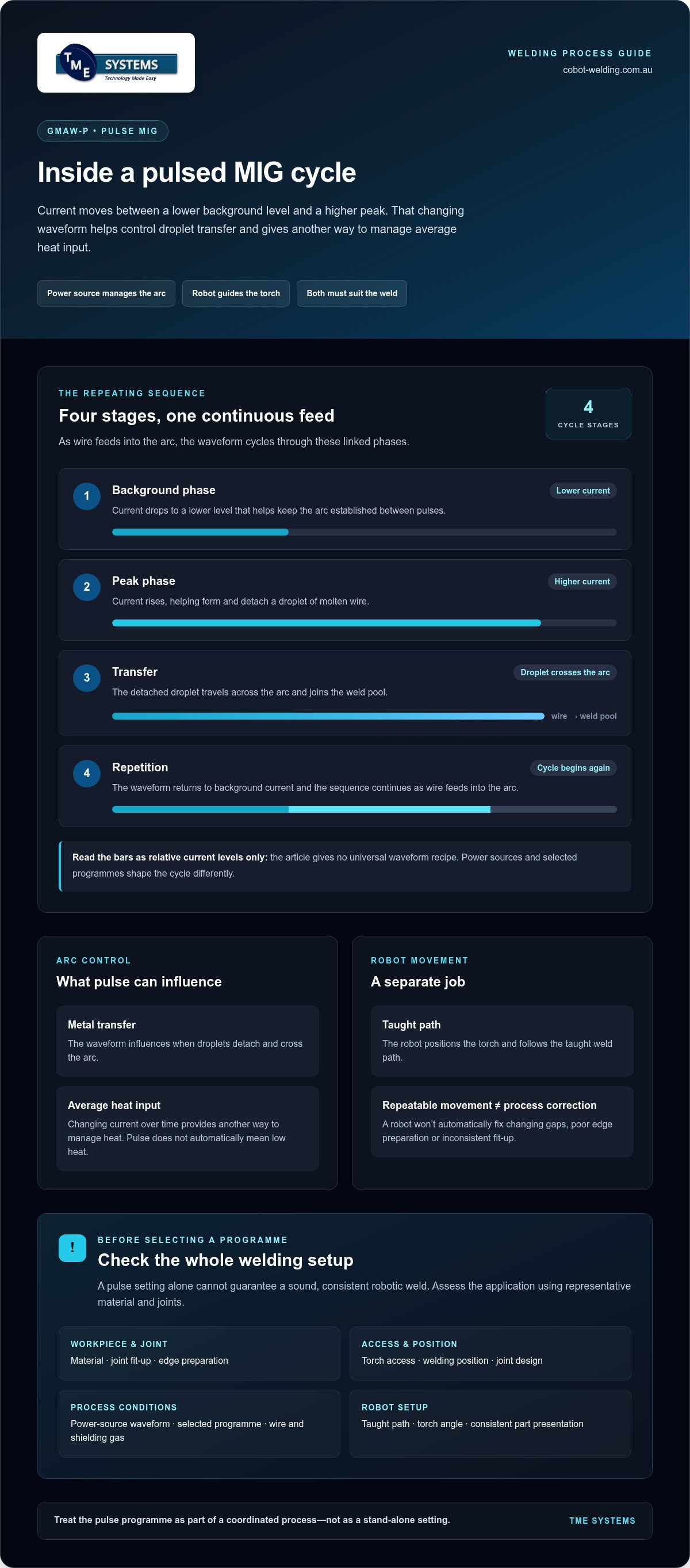
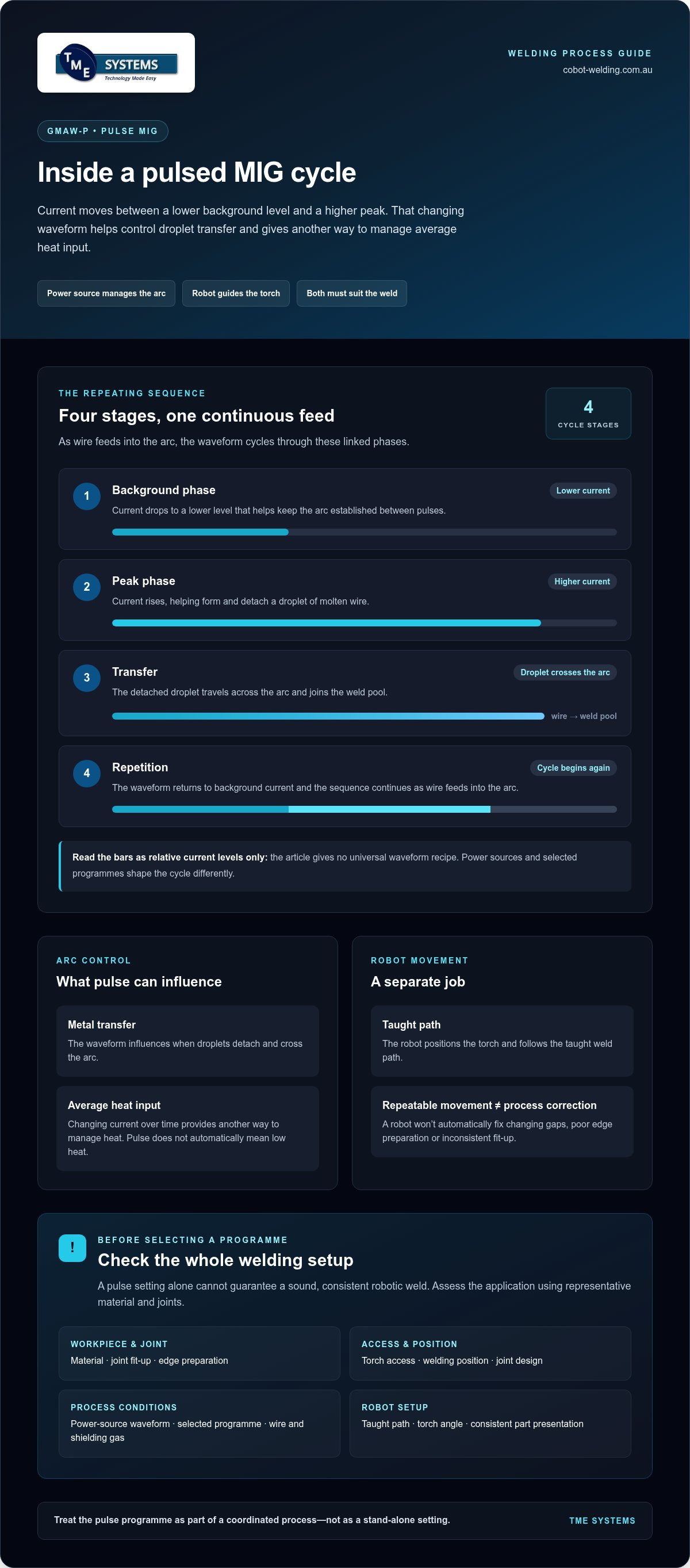
A pulsed programme alternates between background current and peak current. The background phase keeps the arc established at a lower current level. The peak phase raises the current, helping detach a droplet of molten wire and transfer it across the arc towards the weld pool. The cycle then repeats as wire continues feeding.
This controlled transfer can help manage the arc compared with running at one steady current. But there isn’t one universal pulse pattern. The power source and selected programme determine waveform behaviour, including how current changes and interacts with wire feed and arc conditions. Assess the resulting weld on the actual material and joint.
What does the robot add to pulse MIG welding?
The robot adds guided, repeatable torch movement. An operator teaches a weld path, then the robot moves the torch along it while the welding equipment runs the selected process settings. No-code teaching software can let operators teach paths and adjust parameters without traditional programming, keeping practical process knowledge part of the setup.
Repeatable movement is not the same as automatic process control. The power source and its programme control the welding arc; the robot follows the taught motion. Both the settings and movement need to suit the weld.
A robot can repeat a path accurately, but it won’t automatically correct a gap that varies between parts, poor edge preparation or inconsistent fit-up. If the joint shifts or the torch angle is wrong, the robot may repeat the same problem on each cycle. Sound joint preparation, accessible weld positions and a well-taught path remain essential to a reliable automated process.
How the pulsed MIG waveform controls metal transfer and heat
A pulse programme doesn’t simply switch the arc on and off. It shapes current over time to influence when wire droplets detach and cross the arc. Understanding that sequence helps explain what pulse can contribute, and why a waveform setting alone can’t guarantee a sound weld or a consistent robotic result.
Peak current, background current and droplet transfer
The cycle moves through four linked stages:
- Background phase: Current drops to a lower level that helps keep the arc established between pulses.
- Peak phase: Current rises. This increase helps form and detach a droplet from the wire.
- Transfer: The droplet crosses the arc and joins the weld pool.
- Repetition: The waveform returns to its background phase and the sequence continues as wire feeds into the arc.
That’s the practical idea, not a universal waveform recipe. Power sources can shape the current cycle differently, and the selected programme influences how the phases interact. Some controlled pulsed-spray processes aim to transfer droplets regularly, but the precise behaviour depends on the equipment and setup. Treat the programme as a coordinated process, not just a peak-current setting.
Why wire, gas and power-source settings still matter
The waveform works alongside the wire feed, shielding gas and other arc conditions. Wire type and diameter affect how the electrode responds to the pulse; shielding gas also influences arc behaviour and metal transfer. A programme is designed around particular process conditions, so changing a consumable or gas without reassessing the setup can change how the arc runs.
There’s no single wire-and-gas combination to prescribe for every robotic weld. The material, joint, welding position and required weld properties all shape the choice. Use the applicable welding procedure to guide final parameter selection, then assess the weld under representative production conditions.
Pulse can help manage heat, but it isn’t a guarantee
By controlling how current rises and falls, a pulsed process can provide another way to manage metal transfer and average heat input. This may be useful where a steady spray-transfer arc would put more heat into the workpiece than the application can tolerate. But “pulse” doesn’t automatically mean low heat. Travel speed, arc settings, joint design and material all affect the energy delivered to the weld.
Controlled metal transfer creates options, but application-specific settings determine whether those options produce the required weld. A poorly matched programme can still contribute to defects, and pulse alone won’t correct inconsistent fit-up or an unsuitable torch angle. Judge the result by the weld and its inspection criteria, not by the name of the transfer mode.
For robotic welding, process settings also have to work with the taught path and torch access. Collaborative robot welding cells bring process equipment and repeatable movement together, while operator involvement remains valuable for refining the path and assessing trial results.
Pulsed MIG vs short-circuit and spray transfer: what changes?
Each transfer mode moves wire into the weld pool differently, so the useful comparison isn’t simply which one is “best”. As robotic pulse MIG welding explained in practice, selection depends on the job: material thickness, joint type, welding position, access and required deposition rate all matter. The table is a starting point, not a substitute for procedure qualification or trials on representative parts.
| Transfer mode | How metal transfers | Possible fit and trade-offs |
|---|---|---|
| Short-circuit | The wire repeatedly contacts the weld pool, then separates as the arc re-establishes. | May suit some thinner sections and position-sensitive work. Settings and technique need control to achieve the required fusion and weld profile. |
| Pulsed MIG | Current cycles between background and peak levels to help transfer droplets across the arc. | May offer a useful balance of transfer control and heat management for some joints and positions. Results depend on the waveform, settings and application. |
| Conventional spray | Metal transfers as a stream of small droplets while the arc runs in spray transfer. | May suit applications requiring higher deposition, often in suitable positions. The weld pool and heat levels may make it less suitable for some jobs. |
How pulse differs from short-circuit transfer
With short-circuit transfer, the wire touches the weld pool before the arc forms again. Pulse instead uses current peaks to help detach droplets without relying on repeated wire-to-pool contact. Short-circuit can be a practical choice where its characteristics suit the material, joint and position, but results still depend on a suitable procedure and stable setup. Pulse isn’t automatically cleaner or more consistent.
How pulse differs from spray transfer
Conventional spray transfer carries droplets across the arc continuously, while pulsed transfer uses peak phases within a repeating waveform. Pulse may make spray-like transfer possible under conditions where conventional spray isn’t the preferred fit, including some position-sensitive applications. That isn’t a blanket rule: power-source capabilities and the qualified procedure shape what’s achievable for a particular job.
Use the comparison to narrow the options, then test likely candidates against the weld requirements. For example, limited access may rule out a process that otherwise suits the material, while a deposition target may favour a different choice from a thin section requiring careful heat management. Check the complete weld, including fusion, profile and any specified inspection criteria.
A robotic cell can repeat the chosen settings and torch path, but it can’t make an unsuitable transfer mode suitable just by repeating it accurately. Fit-up, torch angle and access still affect the result. Treat the comparison as a way to frame process trials, not a promise of production performance.
When robotic pulse MIG helps, and where setup can limit results
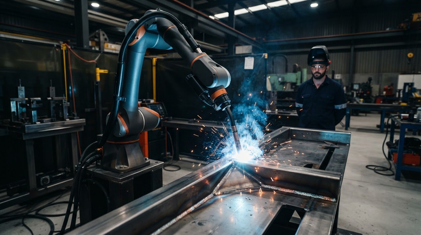
Pulse isn’t automatically the best transfer mode for every robotic weld. It may be worth trialling where controlled metal transfer or reduced spatter could help, but the outcome depends on the complete application. A robot repeats its taught path; it doesn’t make an inaccessible joint easier to reach or correct variable fit-up as it goes.
Assess the weld as a whole. A joint may look straightforward on a drawing, yet a clamp, flange or nearby part can restrict torch access or force an unsuitable torch angle. Material, joint geometry, welding position and cycle requirements all affect whether a pulse setup is practical. A useful result in one position or on one part doesn’t prove it will translate to another.
Application conditions that may favour a pulse trial
Consider a pulse trial if the job calls for controlled transfer or if spatter is a concern under the existing process. Treat those as reasons to test, not promised results. Check whether the torch can reach the joint with a workable angle and travel path, including at starts, stops and changes of direction.
After the procedure and path have been proven, repeatable robot movement may help reproduce the weld. That consistency is valuable only if the taught path suits the real parts and the process settings produce acceptable welds. Include representative parts in the trial, not just an ideal sample.
Common robotic pulse MIG limitations to check
Look beyond the waveform. Check contact-tip condition, torch geometry and cable routing through the full robot movement. Cables that pull, twist or press against the cell can affect access and may add wear. Pulse applications may place particular demands on consumables and power cables, but the effect depends on the equipment, settings and duty cycle.
Before production release, validate weld quality, process stability and wear under the conditions the cell will actually run. Record inspection results and watch for changes across repeated cycles. If the robot can reach the weld only at a compromised angle, revisit part presentation or path planning rather than relying on a programme change alone.
Before production release, validate joint access, torch angle, fit-up, material, welding position, process settings, cycle requirements, weld quality and equipment wear. This checklist helps distinguish a promising pulse trial from a setup ready for repeatable production. Operator involvement matters: accessible teaching tools can help operators refine paths and adjust parameters as trials reveal what needs attention.
For a practical next step, explore collaborative robot welding cells as part of evaluating how a taught path and welding process can work together in your application.
How to evaluate robotic pulse MIG for a real welding job
A pulse programme is worth considering only if it can meet the requirements of the actual weld. A structured trial helps separate what looks promising in theory from what works with your parts, production conditions and inspection criteria. Keep the comparison controlled: changing joint preparation, process settings and the robot path at the same time makes it difficult to identify what affected the result.
A practical sequence for a pulse MIG trial
Work through the evaluation in order, recording decisions and observations as you go:
- 1. Define the weld. Document the material, thickness, joint design, welding position, production needs and required quality criteria. Include access constraints and any relevant acceptance or inspection requirements.
- 2. Prepare representative parts. Use sample parts that reflect production conditions, not just ideal coupons. Keep joint preparation and fit-up repeatable so differences in the weld are less likely to come from part variation.
- 3. Set the procedure and comparison. Choose the applicable welding procedure and identify the process options suitable for the job. Compare them under controlled conditions, holding part preparation and inspection criteria consistent.
- 4. Teach and refine the path. Have an operator check torch access, angle, travel path, starts and stops. Record process settings and path adjustments so the trial can be repeated and reviewed.
- 5. Inspect and review. Document weld quality against the agreed criteria, along with spatter, rework, consumable condition, process stability and repeatability. Use those observations to decide whether pulse meets the job’s needs, rather than assuming the mode itself predicts the result.
Consistent records make the trial useful beyond the first sample. If a change is needed, adjust a defined part of the setup, then repeat the test and compare results. This gives the team a clearer basis for refining the procedure or path before production release.
Where cobot integration and operator training fit
Once the welding procedure has been assessed, integration connects the power source, robot movement, part presentation and work sequence into a practical workflow. Operators remain central: their welding knowledge helps them judge the joint, teach an appropriate path and make informed parameter adjustments. Training supports that expertise; it doesn’t replace it.
No-code teaching software can help operators refine paths without traditional programming. For a closer look at this approach, see the guide to no-code robot welding software. Cell-level planning matters too, since part handling, torch access and process equipment all affect the application; the guide to collaborative robot welding cells covers that wider context.
TME Systems supplies and integrates collaborative robot welding cells, with operator onboarding to support the transition from trial to taught workflow. A mobile demonstration can provide a practical next step for exploring how the process and robotic setup may work together.
Make your next welding decision a practical one
Use robotic pulse MIG welding explained as a starting point for a focused discussion about production priorities, not as a preset answer for every job. Identify a representative weld and define what a successful result needs to achieve for your team. That gives operators, welding specialists and automation partners a shared basis for planning what to assess.
As your requirements take shape, consider how the cell, teaching approach and operator support fit together. TME Systems supplies and integrates collaborative robot welding cells for manufacturing, with no-code teaching software that supports weld-path teaching and parameter adjustment without traditional programming. The goal is to make automation workable for the people responsible for running and refining it.
Explore collaborative robot welding solutions and discuss how a robotic setup could fit your manufacturing needs. A clear starting point and the right people involved can make the path into automation more manageable. Your team can build confidence one considered decision at a time.
Frequently Asked Questions
What does pulse mean in robotic MIG welding?
Pulse means the power source varies current between peak and background levels to influence the arc and metal transfer. The robot supplies the programmed torch movement; it doesn’t generate the pulse. In robotic pulse MIG welding explained simply, these are separate functions coordinated in one cell. If a production adjustment is needed, identify whether it belongs to the welding programme or the robot path before changing either.
Is pulsed MIG welding the same as spray transfer?
No. They’re related transfer approaches, but conventional spray uses different current behaviour from pulsed transfer. A power source may support both, yet the settings and welding procedure determine what’s suitable. For instance, don’t assume a mode that works on a flat test piece will suit a constrained weld position. Compare suitable options on representative parts, then assess each against the documented acceptance requirements.
Can robotic pulse MIG welding be used on aluminium?
Yes, pulsed MIG is used in some aluminium applications, but that doesn’t establish suitability for every job. A change in alloy, thickness or joint design may call for a different wire, shielding gas or programme. Confirm the equipment supports the required process, then trial it on a representative joint with the intended torch approach. Assess the result against the applicable welding procedure and its acceptance criteria.
Does pulse MIG welding eliminate spatter?
No. A well-matched pulse setup may reduce spatter in a particular application, but it can’t promise a spatter-free weld. Surface condition, consumables and process settings can all affect the result. For a useful production comparison, inspect the same areas across representative parts and record cleanup or rework consistently. This gives the team a better basis for judging a change than relying on the appearance of a single weld.
Do you need a special welding machine for pulse MIG?
Yes. The power source must be capable of producing a suitable pulsed waveform and supporting a programme for the intended application. A machine that only supports conventional transfer modes won’t become pulse-capable through robot programming. Check the wider setup too, including wire-feed equipment, torch and integration with the cell. Assess the complete configuration against the applicable welding procedure before building a production path around it.
Can a robot compensate for poor joint fit-up?
Not by itself. A robot repeats its taught motion, but part variation can shift the joint away from the torch’s expected path. If a component sits proud or a gap varies, the same movement may produce different results. Suitable fixtures, consistent preparation and a validated path help manage variation. Sensing or correction functions need to be configured for the application, so don’t assume they’re inherent in pulse welding or robot control.
Does pulsed MIG require different contact tips or maintenance?
Possibly. Wear depends on the waveform, operating conditions and setup, so there’s no universal contact-tip replacement interval for pulse MIG. Follow equipment guidance and inspect contact tips and power cables during representative production runs. Record visible wear or changes in arc stability, then review them alongside process conditions. Base maintenance intervals on the equipment instructions and observed condition, rather than applying a blanket rule to all pulsed applications.