
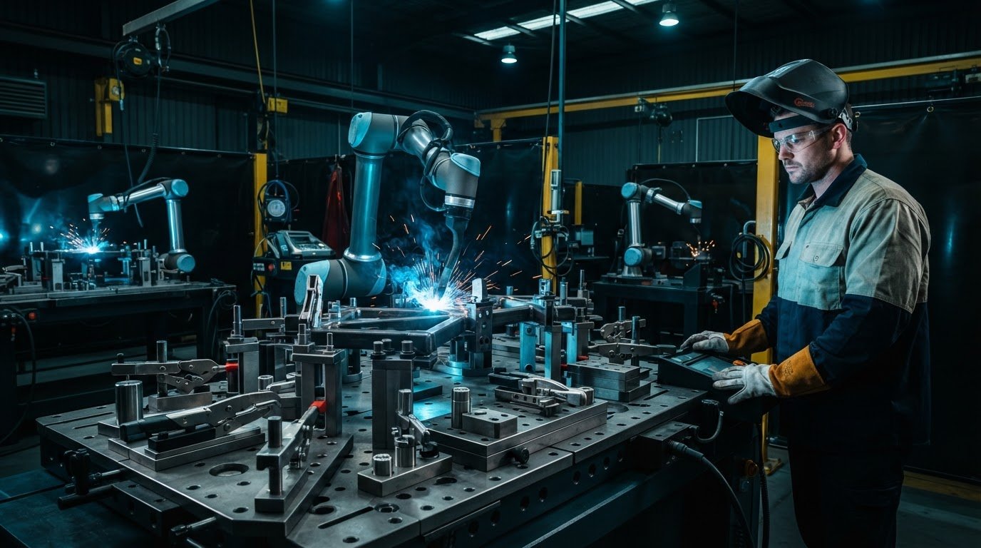
A more capable robot won’t compensate for a part that shifts in its fixture. Reliable robotic welding starts with repeatable workholding, so choosing robotic welding fixtures and tooling matters just as much as selecting the robot and welding equipment.
If you’re weighing up a dedicated fixture, adjustable tooling or a simpler locating setup, start with the parts and jobs you need to run. Poor location or clamping can lead to inconsistent welds and rework. An overly complex fixture can slow changeovers and make everyday operation harder. The right approach balances repeatability with your production mix and the way operators load each part.
This guide gives you a practical framework for comparing fixture options, from locating and clamping to weld access, changeovers and operator use. You’ll also find what to include in a tooling brief and how to trial a setup with representative workpieces. These steps help you assess how the fixture will fit into the wider welding system and workshop workflow, whether you’re planning a collaborative robot welding cell or refining an existing process.
Key Takeaways
- Separate the fixture’s locating and support functions from its clamps, then plan torch access to each weld.
- Use a clear design sequence: define datums, locate the part, clamp it, then check torch angle, approach and clearance.
- Compare dedicated, adjustable and modular robotic welding fixtures and tooling against your part range, changeover needs and repeatability goals.
- Prepare drawings, tolerances, weld details, loading method and job variation before trialling and validating the setup.
- Assess how the fixture will work with the robot, welding equipment, teaching software and operators as part of the wider production workflow.
Why robotic welding fixtures and tooling determine repeatability
A robot can repeat a programmed movement, but it can only weld the part presented to it. If each workpiece sits differently, the torch follows the same path relative to the robot, but not necessarily relative to the joint. That difference can change joint fit-up, torch position and the finished weld. Repeatable robot motion is useful only when the workpiece is positioned consistently.
Reliable robotic welding depends on stable part location: the fixture must present each workpiece consistently while leaving the weld accessible to the torch. In robotic welding, the robot, welding equipment and workholding operate as parts of one process. The fixture locates and supports the workpiece. Locating features establish where it sits; clamps hold it there. Torch access is a separate design requirement, but it needs to be considered alongside both.
What does a robotic welding fixture do?
Locating points give the operator a consistent way to position a part against known surfaces or stops. Clamps keep it seated during welding without distorting it or blocking the joint. Together, the fixture and its components form the tooling, which must also leave a clear route for the torch to approach and travel along each weld. The layout should suit the part, weld sequence and cell arrangement, not just hold the workpiece firmly.
When does existing workholding need a rethink?
Repeated manual alignment, variable fit-up or frequent repositioning are practical signs that existing workholding may need review. A robot can trace its programmed path consistently, yet small changes in how a part is loaded can move the joint away from that path. Clamps can also obstruct the torch or force an awkward approach. These problems affect repeatability even when the robot’s motion is unchanged.
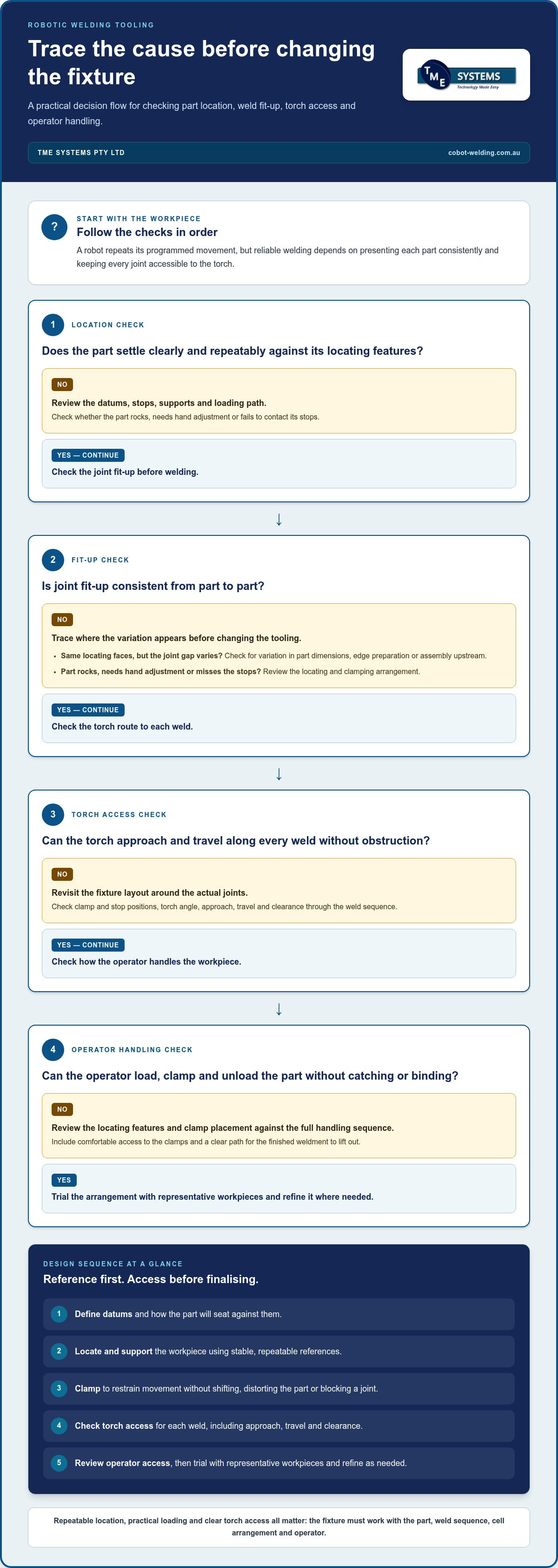
Separate workholding problems from variation earlier in the process. A fixture can locate parts consistently, but it can’t correct inconsistent dimensions, edge preparation or assembly. Compare several representative parts and note where the variation appears before changing the tooling. For example, if parts seat against the same locating faces but the joint gap still varies, the cause may be upstream. If a part rocks, needs hand adjustment or fails to contact its stops, review the locating and clamping arrangement.
- Observe loading: Does the part settle into position clearly and repeatably?
- Check the joint: Is fit-up consistent before welding, or does it vary from part to part?
- Review access: Can the torch reach the weld without the fixture or clamps obstructing its approach?
- Trace variation: Does the issue follow the workpiece, its preparation or the way it is held?
These checks help focus the next design decision. A well-considered setup supports repeatable location, practical loading and weld access, while giving operators a clear way to present each part.
How to design robotic welding tooling for part location and weld access
A practical design sequence keeps the workpiece, weld and robot motion in view from the start. First, define the datums: the stable reference surfaces or features that establish position. Then locate the part against those references, decide how to restrain it, and check whether the torch can reach every joint along the intended weld sequence. Include access for loading and unloading, so the setup works for the operator as well as the robot.
Locating features should reference stable, repeatable part datums, not surfaces that vary from one workpiece to the next. If the reference changes, the part’s position can change with it, even when the fixture itself stays the same.
How should a fixture locate and clamp a weldment?
Choose datum features that are practical to find and contact consistently, such as a defined edge, face or hole shown on the part drawing. The fixture’s stops and supports should guide the workpiece into position without relying on the operator to judge alignment by eye. Clamps then restrain movement during welding. Their placement and pressure need to hold the part securely without shifting or distorting it.
Check the full handling sequence, not only the clamped position. Can the operator load the part without catching it on a stop? Can they reach and operate the clamps comfortably? Can the finished weldment lift clear without binding? These questions may reveal that a locating feature or clamp needs repositioning before the fixture layout is finalised.
How do torch access and weld sequence affect tooling?
Map the torch’s approach and travel around each joint before finalising fixture features. Consider the required torch angle, joint visibility and clearance throughout the movement, including any reorientation between welds. A clamp might hold the part well but block the torch’s approach. A tall stop could restrict robot movement near a corner. There’s no single layout for every weldment, so assess access against the actual joints and cell arrangement.
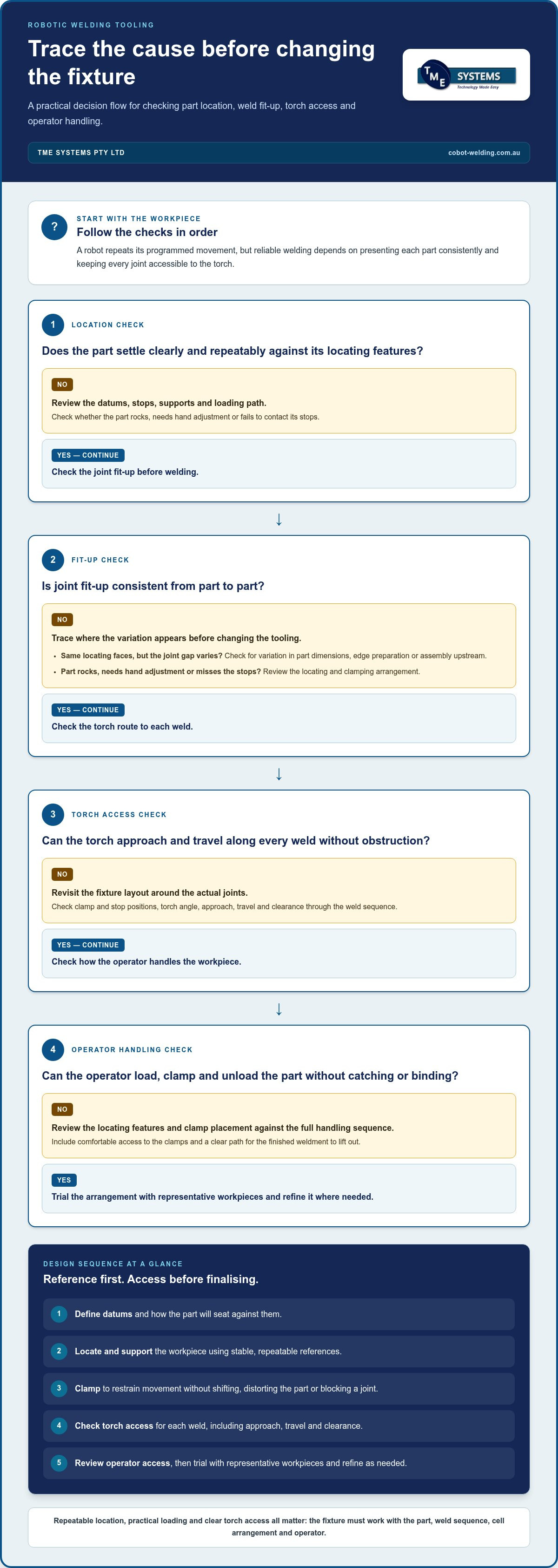
Work through the design in sequence:
- Identify the reference datums and how the part will seat against them.
- Position supports and clamps to restrain the workpiece while keeping joints clear.
- Trace the torch approach, travel and clearance for each weld in order.
- Review operator access for loading, clamping and unloading.
- Trial the arrangement with representative workpieces and refine it where needed.
Trialling matters because parts can vary, and welding heat can contribute to movement or distortion. A fixture that suits one sample may not handle the normal range of incoming workpieces or behave as expected after welding. Compare representative parts, observe fit-up before and after the sequence, and note where the torch path or clamping arrangement needs adjustment. This helps distinguish a tooling issue from variation in the part or its preparation.
For a practical review of how tooling fits into a complete cell, discuss your parts and welding setup as part of a project conversation.
Dedicated, adjustable or modular tooling: compare the trade-offs
The right fixture style depends on how often a part runs, how much the product range varies and how changeovers fit into the shift. Dedicated tooling is built around a particular part or assembly. Adjustable tooling changes position to accommodate related parts, while modular tooling uses components that can be rearranged for different setups. Flexibility can help with a varied job mix, but it may add setup steps. Compare the options against actual production requirements rather than assuming one approach is best.
| Tooling approach | Strengths | Limitations | May suit |
|---|---|---|---|
| Dedicated | Simple, consistent setup for a defined part | Less adaptable when the part or job changes | Stable repeat production |
| Adjustable | Can accommodate a family of related parts | Needs clear adjustment and setup practices | Regular variation within a known part range |
| Modular | Components can be rearranged for different jobs | Reconfiguration and storage need planning | Varied work where shared tooling components are practical |
When does dedicated tooling make sense?
Dedicated tooling can suit work where the part design and production requirements remain stable. A purpose-built arrangement can make loading straightforward, but may be less convenient if product variation or frequent changeovers are part of the work. Repeatability still depends on operators loading parts consistently and using the locating features as intended. Consider how often the fixture will run and what happens when the job changes.
When are adjustable or modular fixtures worth considering?
Adjustable tooling can support related parts by allowing locating or clamping positions to change. Modular tooling can be reconfigured from shared components. Both approaches can reduce the need for wholly separate setups, but they also bring decisions about adjustment, reassembly and correct positioning. If a changeover is rare or takes considerable effort, the flexibility may bring little practical value. Include the operator’s setup tasks in the comparison.
How should batch mix influence the comparison?
Look at the production mix over a representative planning period: which parts run regularly, which appear occasionally and how much notice a changeover allows. Consider not just the number of part types, but also how similar their joints, locating references and loading methods are. A small family with common features may suit adjustable tooling. A varied mix may call for modular components, while stable repeat work can favour a dedicated setup.
Include operator effort and storage in the decision. A fixture that’s quick to change but difficult to handle, identify or store may disrupt the workflow. For each option, record the changeover tasks, how the setup is checked and where unused tooling will be kept. These details help show whether added flexibility will be used or simply add complexity.
Fixture choice also affects the wider cell layout, operator interaction and how work moves through production. Review those factors alongside the tooling approach when planning collaborative robot welding cells. A useful comparison of robotic welding fixtures and tooling ties each option to actual parts, job frequency and changeover needs, then tests the preferred setup with representative work.
How to specify and validate robotic welding fixtures before integration
A clear tooling brief gives the project team a shared reference before fixture design and cell integration begin. It captures the parts, welds, production mix and operator tasks the setup needs to support. A structured trial can then show whether the proposed fixture works with representative workpieces and the wider cell before production handover.
What information belongs in a tooling brief?
Include current part drawings and relevant tolerances, materials, part families and weld-joint locations. Describe the expected job mix and changeover pattern, how operators load and unload parts, and the space available for the fixture. Note existing welding equipment and workflow interfaces. These details help the integration team assess how the tooling fits the production environment rather than treating it as a standalone device.
Use this workflow to move from initial review to acceptance:
- Review representative parts. Gather drawings and physical examples that reflect the part range and normal variation.
- Define the requirements. Record location, clamping, weld access, loading method, changeovers and interfaces with existing equipment.
- Trial the proposed setup. Load representative workpieces and assess fit-up, torch access and how consistently the parts seat.
- Observe operators. Include the people who will use the fixture, and watch the loading and unloading sequence in practice.
- Adjust and retest. Record issues, refine the fixture and repeat the checks against the agreed requirements.
- Agree acceptance. Document the project team’s acceptance criteria and results before production handover.
How can a fixture be trialled before production?
A useful trial checks more than whether one sample can be clamped. Run representative parts through the intended loading and welding sequence, then assess location, fit-up, joint access and repeatability. Include operators so they can identify awkward handling or unclear setup steps. If the fixture needs adjustment, repeat the relevant checks and record the outcome against the project team’s agreed acceptance criteria.
How does tooling interact with cell safety?
Assess the fixture as part of the complete robotic welding cell, not in isolation. Consider pinch points at clamps, hot workpieces after welding and how operators move around the setup during loading, unloading and other operating modes. The cell risk assessment should account for the robot, welding equipment, fixture and work practices together. Identify the Australian requirements and standards applicable to the specific system as part of project planning.
Good validation makes the tooling brief practical by connecting part requirements with operator tasks, equipment and the complete cell. TME Systems Pty Ltd integrates welding systems with existing equipment and production workflows. Discuss your fixture requirements for a robotic welding project with the wider setup in view.
Integrate fixtures and tooling with a robotic welding solution
A fixture doesn’t operate on its own. Its position and layout affect how the robot reaches the weld, how the torch approaches the joint, how weld paths are taught and how operators load parts. The welding equipment and cell layout matter too. Planning these elements together helps the tooling fit the production process, rather than creating a fixture that works by itself but is awkward to use once installed in the cell.
TME Systems Pty Ltd integrates robotic technology with existing welding equipment and factory workflows. Fixture requirements can be considered alongside the robot, welding equipment and software as part of the wider system. This joined-up view helps bring equipment, process and production needs into the same integration plan.
Why assess tooling as part of the complete welding system?
Check the fixture against the robot’s working area and the weld sequence, not just the part’s resting position. A support or clamp may affect torch clearance, while a change in how a part is loaded can influence access to the joints. No-code teaching software lets operators teach weld paths without writing complex code, but the tooling still needs to present the workpiece in a practical position for those paths. Consider the surrounding workflow too, including how parts arrive at and leave the cell.
What should operators be involved in before handover?
Operators can identify practical issues that aren’t obvious from drawings alone. Include them in reviews of part loading, clamp use and changeover steps, then build those tasks into onboarding. With no-code teaching software, operators can teach weld paths without writing complex code. Onboarding helps them understand how path teaching and fixture setup fit into everyday cell use. TME Systems Pty Ltd provides operator training and onboarding for collaborative robot welding systems.
What are the next steps for assessing a fixture project?
Start with representative parts, current drawings and a clear picture of production constraints. Note the job mix, existing welding equipment, loading and changeover steps, and any space or workflow considerations that could affect the cell. Bring those details into the same discussion as fixture needs and integration requirements, so the proposed setup reflects how work is actually done.
A mobile demonstration can help your team explore a representative welding application and consider how tooling fits the process. Book a mobile welding robot demonstration to discuss a practical example, or discuss your robotic welding project with TME Systems Pty Ltd. Reviewing robotic welding fixtures and tooling alongside equipment and operator needs gives the project team a practical basis for planning the cell.
Turn your fixture requirements into a practical next step
Bring the production details into the conversation. Gather a representative part, its drawing and the constraints your team works with, then consider how the tooling should fit the existing process. This gives you a grounded starting point for discussing robotic welding fixtures and tooling as part of a complete automation project.
TME Systems Pty Ltd integrates robotic technology with existing welding equipment and factory workflows. A mobile demonstration lets your team explore a representative application, while operator onboarding supports the people who will use the cell and tooling day to day. The aim is a setup that makes sense not just on paper, but in your production environment.
Discuss your robotic welding fixture and integration requirements with TME Systems Pty Ltd to plan a setup around your production needs. Bring your part details and workflow requirements to start a practical project conversation.
Frequently Asked Questions
Can existing welding fixtures be adapted for robotic welding?
Yes, an existing fixture may be adaptable if it presents parts consistently and gives the robot suitable torch access. Review its locating surfaces, clamp positions, condition and fit with the cell layout. For example, a manual jig with handles or stops in the torch path may need changes before it can support an automated weld sequence. Trial the modified setup with representative parts before relying on it in production.
How do you stop a part moving during robotic welding?
Use locating features and supports to seat the workpiece, then clamps to restrain movement without forcing the part out of shape. Check that the part stays seated as clamps are applied and that supports are positioned for the loads created by the weld sequence. If a component can flex, trial the setup through welding and cooling, then inspect whether it shifts or distorts.
Can magnetic clamps be used in a robotic welding fixture?
They can be considered for suitable ferrous parts, but their suitability depends on the component, weld locations and cell arrangement. A magnetic clamp may not suit every shape or provide the restraint needed for a particular weld sequence. Check that it won’t obstruct torch access or complicate loading, then trial it with the actual workpiece and welding setup before adopting it for repeat production.
What information should I provide for a robotic welding fixture assessment?
Provide current part drawings, relevant tolerances, material details and weld locations. Include representative parts if available, plus information about batch mix, job changes and how operators currently load and secure each workpiece. Note the existing welding equipment and any space or workflow constraints around the cell. These details help assess robotic welding fixtures and tooling against the actual production task.
Do robotic welding fixtures need to be custom-made for every part?
No. Parts with shared locating references and similar geometry may be handled with adjustable or modular tooling rather than separate dedicated fixtures. The key is whether the tooling can position each part reliably without making setup confusing or slow. For instance, related brackets may share a base arrangement, while different joint positions may call for separate locating or clamping elements. Confirm the fit with trials across the part family.
How often should robotic welding fixtures be inspected?
There isn’t one inspection interval that suits every fixture. Set a routine based on production use, operating conditions and the fixture’s maintenance guidance. Operators can look for visible wear, loose components, damaged locators or weld spatter that affects seating as part of normal checks. Inspect after a collision, unexpected movement or repair, and record issues so changes in fixture condition don’t go unnoticed.