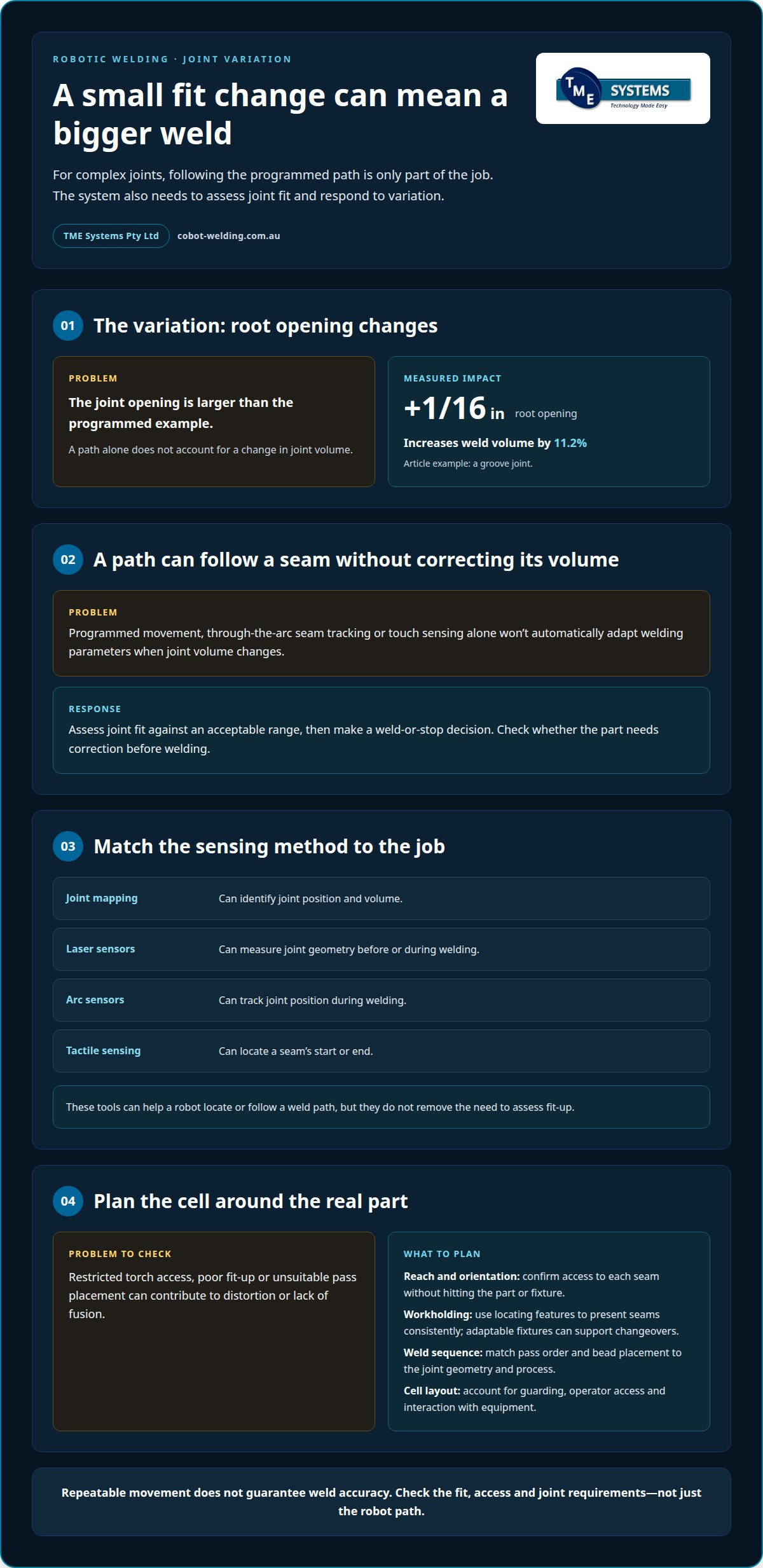

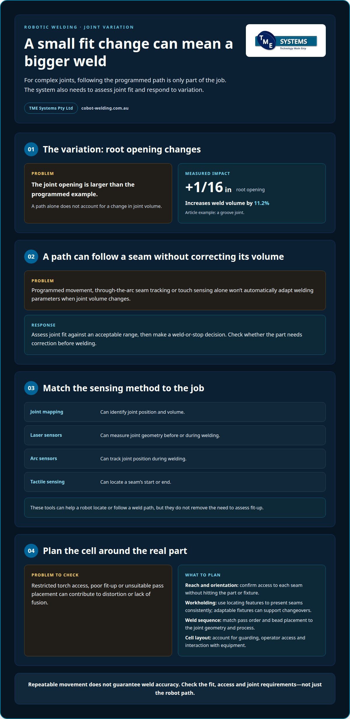
What if a small change in joint fit alters the weld more than the programmed path can handle? Robotic welding for complex joints can accommodate part variation when the system locates the joint, assesses its fit and adjusts the weld path or parameters. In an example groove joint, increasing the root opening by 1/16 inch increases weld volume by 11.2 per cent. A programmed path alone, or seam tracking and touch sensing alone, won’t automatically account for changes in joint volume.
It makes sense to be cautious: repeatable welds depend on whether parts arrive in a condition the system can handle, not just on the robot’s movements. This guide explains how sensing and joint analysis respond to variation, how CAD simulation can help plan weld paths, and what to consider when selecting a robot or cobot for mixed production. You’ll also see where automation can help and why the right setup depends on joint access, fit-up and how often parts or jobs change.
Key Takeaways
- Assess joint access and torch orientation alongside robot reach to judge whether complex welds are practical across varied parts.
- Use CAD simulation to review weld paths and identify access or collision issues before programming on the shop floor.
- Choose between a robot and cobot by weighing production mix, changeovers, operator involvement and the work each system must handle.
- Match the welding process to joint geometry, material and finish requirements; the most suitable option depends on the job.
Can robotic welding work for low-volume, high-mix production?
Yes, robotic welding for complex joints can suit mixed production when parts, fixtures and programs support planned changeovers. The key is to match each job family to the cell’s reach, joint access and acceptable fit-up range.
Robot Reach and Joint Orientation
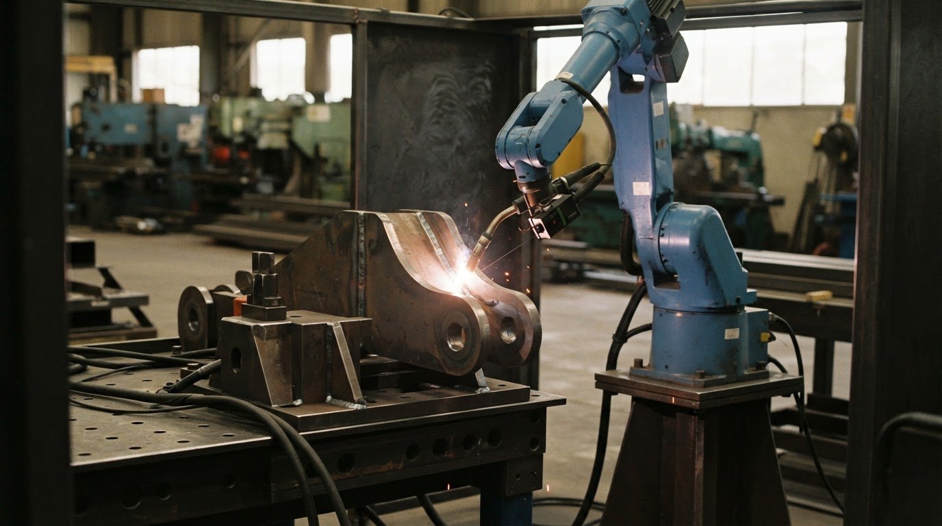
Robot reach and orientation describe whether the torch can access a seam at a suitable angle without hitting the part or fixture. A seventh axis mounted in the robot base enables horizontal movement up to 550 mm, helping position the arm along larger workpieces. Manual welding lets a skilled welder reposition directly, while robotic welding relies on programmed movement and suitable access. Repeatability describes consistent movement, not guaranteed weld accuracy or production rates.
Joint Tolerances and Weld Decisions
Tolerance analysis assesses joint fit against an acceptable range and supports a weld-or-stop decision. In an example groove joint, increasing the root opening by 1/16 inch raises weld volume by 11.2 per cent. Through-the-arc seam tracking and touch sensing alone don’t automatically adapt welding parameters to changed volume. Joint mapping can identify joint position and volume; laser sensors can measure geometry before or during welding.
Arc sensors can track joint position during welding, while tactile sensing can locate a seam’s start or end. These tools help a robot follow a weld path, but they don’t remove the need to assess fit-up.
Custom Cells and Workpiece Handling
A custom cell brings together the robot, fixtures and material handling for the parts being welded. For a family of frames, locating features can help present each seam consistently, while adaptable workholding supports changeovers. Australian welding standards and workplace safety requirements depend on the process, equipment and site risk assessment. Cell planning needs to account for guarding, operator access and interaction with equipment.
Weld Passes and Fillet Joint Recognition
Passes and layer sequences determine the order and placement of beads in a joint. The program must suit the joint geometry and welding process. Fillet recognition can distinguish arrangements such as T-joints, lap joints and corner joints. In robotic welding for complex joints, poor fit-up, restricted torch access or unsuitable pass placement can contribute to distortion or lack of fusion. Joint checks help identify when a part needs correction before welding.
CAD-based welding simulation and programming
CAD-based welding simulation uses a digital part model to plan robot movement before production. The programmer defines the joint line, workpiece position, torch and fixture, then creates a proposed weld path. For a boxed frame, this lets the team assess whether the torch can reach internal seams without hitting a clamp or another face.
Simulation can test the sequence as well as the path. The programmer can model approach and retreat movements, transitions between welds, and robot repositioning. If the torch cannot maintain a suitable orientation around a corner, the sequence or workpiece presentation can be revised before setting up the physical cell. This can make planning more manageable when production includes several part designs.
Next, the virtual path is translated into controller instructions and welding parameters. These may include travel speed and other process settings selected for the joint and welding process. Library-based welding data can help create a path and reduce the number of reference positions that need teaching. The operator still needs to assess whether the proposed path suits the actual part and weld requirements.
A CAD model represents intended geometry, not every variation in a fabricated component. If a part is misaligned or its joint differs from the model, the simulated path may not match the real seam. Simulation can identify access and collision issues, but it does not replace assessing fit-up or validating the weld on the physical workpiece. A useful handover compares the programmed path with the part, then refines positions or parameters as needed.
For mixed production, keep models, weld sequences and program versions organised by part. That makes it easier to identify which program belongs to a specific job and update it when geometry changes. A considered simulation-to-cell planning approach helps connect digital programming decisions with practical access, fixtures and operator needs.
Robot and cobot welding system selection
Choose a welding system by matching its movement, access and operating setup to the parts. A conventional industrial robot may suit a dedicated cell with repeatable parts and a defined cycle. A collaborative robot may suit production where operators need to work more closely with the equipment, provided the cell design supports that workflow.
Start with the hardest weld, not the easiest. For a frame with internal corners, check that the arm can reach every seam while keeping the torch angle and cable clear of fixtures. Payload matters too: the robot must handle the torch and any mounted sensors or tooling. A reach figure on a specification sheet alone won’t establish access around the actual workpiece.
Then assess how often jobs change. A stable product family may justify fixed fixtures and dedicated weld paths. Frequent changeovers put more emphasis on accessible setup, clear part location and straightforward program selection. Seam tracking can help follow a joint whose position varies, but sensing doesn’t replace a suitable robot configuration or a sound weld procedure.
Consider these factors together rather than selecting on arm type alone:
- Joint access: map torch approach, orientation and clearance for each critical seam.
- Part mix: identify which components share a fixture and which need separate setups.
- Operator involvement: decide whether the operator loads parts, changes programs or works alongside the cell.
- Expansion: allow for the addition of a positioner, sensor or handling equipment if the production task requires it.
A cobot is not automatically the better choice for mixed production, just as a larger industrial robot isn’t automatically more capable. Compare both against the same part, weld sequence and operator workflow. A practical trial can show whether the torch reaches the joint, changeovers are manageable and seam tracking supports the process. The right selection balances weld access, production needs and the work operators still need to do.
What robotic welding processes are best for complex joints: MIG, TIG, laser or hybrid?
No single process suits every complex joint. Choose by weighing material, thickness, joint preparation, access and required finish. For example, a deep groove in a structural component presents different demands from a thin stainless-steel corner seam. The robot must also hold a suitable torch angle and maintain the process across the joint.
MIG welding is often considered for production where deposition rate and a practical range of applications matter. It uses continuously fed wire, so the program must coordinate travel speed, wire feed and torch position. On a fillet weld, consistent joint access and stable fit-up help the robot place the bead as intended. Variations in the gap can affect the weld, so sensing and process setup matter.
TIG welding offers greater control over the weld pool, which can suit applications where appearance or heat input needs close attention. That control also requires coordination of the torch, filler addition and travel. A tight corner or changing seam angle can restrict access, so review the complete torch path, not just the joint line.
Laser welding concentrates energy in a narrow area, making joint fit and beam alignment important. Even a small mismatch between parts can affect whether the beam reaches the intended seam. Hybrid welding combines laser and arc processes, but adds equipment and process interactions that need to be integrated into the cell. It isn’t automatically the better option for a difficult joint.
Compare candidate processes on the actual part. Examine joint geometry, material thickness, access, fit-up variation, required bead and the effects of heat. Then establish suitable parameters and assess weld samples against the job’s quality requirements. A process that performs well on a straight seam may not suit an inaccessible corner or variable root opening. Discuss welding process integration for your application and production mix.
TME Systems: Collaborative Robot Welding Cells
TME Systems helps Australian manufacturers assess collaborative robot welding when complex joints, frequent changeovers or operator-led teaching make automation worth considering. Its Collaborative Robot Welding Cells bring robotic welding into a production setup, while No-Code Teaching Software lets operators teach weld paths and adjust parameters without traditional programming.
For a mixed-production workshop, the practical question is how the cell fits the parts, welding process and operator workflow. TME Systems provides welding system integration to connect the welding task with the cell setup, and a Mobile Demo System for hands-on evaluation. Operator onboarding and training support the people who will use the system.
If you’re assessing a cobot cell for your weld joints or production mix, contact TME Systems to discuss your application.
Turn a representative weld into your next decision
A practical assessment of robotic welding for complex joints starts with a representative job, not an abstract automation target. Choose a part that reflects the access challenges, fit-up variation and changeovers your team encounters. This keeps the discussion focused on the actual seam, the operator’s workflow and what the cell must accommodate.
Bring together the details that shape the decision: part geometry, material, joint preparation, required weld quality and the range of jobs in the mix. Include the awkward seam, not only the straightforward one. These details help clarify what needs evaluation and where human judgement remains important, from handling parts to recognising when fit-up needs attention.
Use that job as a starting point for a focused conversation about your production requirements and possible next steps. Talk with TME Systems about your welding application and move forward with a clearer view of what your workshop needs.
Frequently Asked Questions
Can a robot compensate for part variation?
Yes, a robot can respond to variation within the limits of its sensing and welding setup. For example, seam tracking can correct a displaced joint, while joint mapping can inform weld adjustments. If a gap falls outside the accepted fit-up range, stopping may be more appropriate than welding. Sensors can’t compensate for every change in joint geometry or weld volume.
What parts are good candidates for robotic welding?
Parts with repeatable fit-up, stable fixturing and accessible weld seams are strong candidates. A batch of similar brackets, for example, gives the robot a consistent joint location and torch approach. High-mix, low-volume work can also suit automation when the right part families are chosen. Parts that need frequent manual repositioning or extensive fit-up correction require careful assessment before programming.
How do 6-axis and 7-axis welding robots handle complex joint geometries?
A 6-axis robot uses its articulated joints to position and angle the torch around a workpiece. A 7-axis arrangement adds another movement axis, which can reposition the arm or workpiece and improve access around long seams or obstructed areas. The extra axis doesn’t automatically solve every access problem: fixture placement, torch clearance and the required weld angle still shape the workable path.
How do you program and simulate robotic welding paths for complex joints?
Start with the part geometry and identify each seam, torch approach and travel direction. CAD simulation can then test the proposed path against fixtures and nearby surfaces, helping identify collisions or unreachable joints. After transferring the program to the robot, compare its path with the physical part and refine it through testing. Simulation informs programming, but the real component and welding process still need assessment.
What joint preparation, fixturing and tolerances are needed for robotic welding?
Prepare the joint to suit the welding procedure, with consistent edges, alignment and root opening across the part family. Fixtures should locate the workpiece securely without blocking torch access or sensors. Define acceptable fit-up limits based on the required weld quality, then use joint analysis to distinguish parts that can proceed from those needing correction. Tolerances vary with joint design, process and sensing method.
What accuracy, repeatability and production rates can robotic welding achieve on complex joints?
Repeatability means consistent robot movement, but it does not guarantee weld accuracy or production rates. Accuracy depends on factors such as joint fit-up, access and whether sensing and joint analysis can accommodate part variation.