
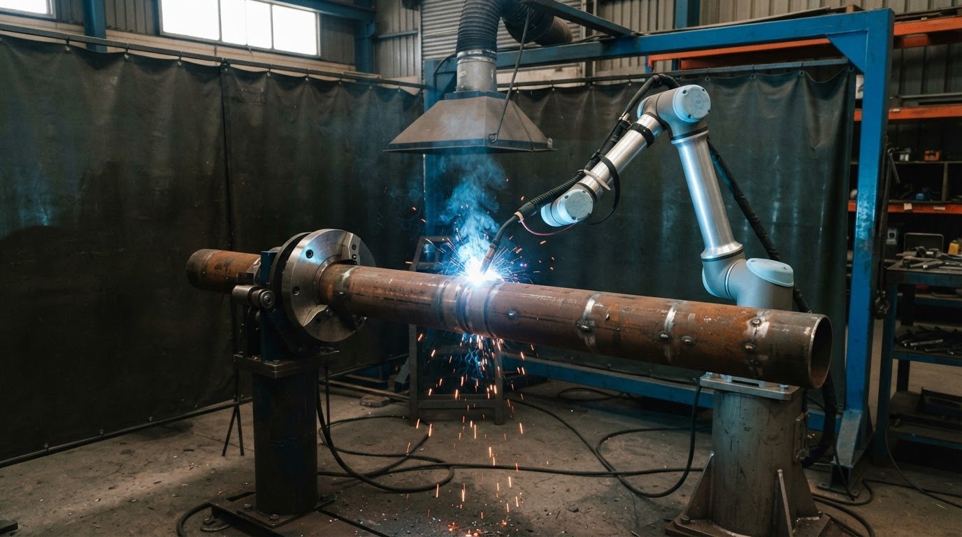
A pipe welding robot coordinates the torch with the pipe or tube, sometimes using a positioner to rotate the workpiece and keep the joint accessible. Robotic welding for pipe and tube can suit repeatable work when part dimensions, wall thickness and joint fit-up align with the process and cell setup. It may struggle if gaps or seam positions vary beyond the system’s capabilities.
Automation doesn’t replace sound preparation or skilled operators. It makes repeatable movement and settings easier to manage. This article explains how pipe welding robots work and how pipe size, wall thickness, the work environment and production demands affect suitability and throughput.
You’ll also learn why consistent joints matter, how sensing and monitoring can help a robot follow a seam, and what to consider when planning changeovers. The goal is to help you assess whether a robotic cell fits your production work and understand the practical trade-offs before moving ahead.
Key Takeaways
- Assess the cell’s surroundings and seam variation together: sensing can help the robot stay on track, but the work environment still affects setup.
- Consistent dimensions and careful joint preparation can help make robotic welding a better fit.
- Plan throughput around loading, changeovers and operator attention. With several positioners in use, one person can operate up to five.
- Understand how the robot, torch and positioner coordinate, then consider whether collaborative welding cells and no-code teaching software fit your production needs.
Operating environment and IP rating
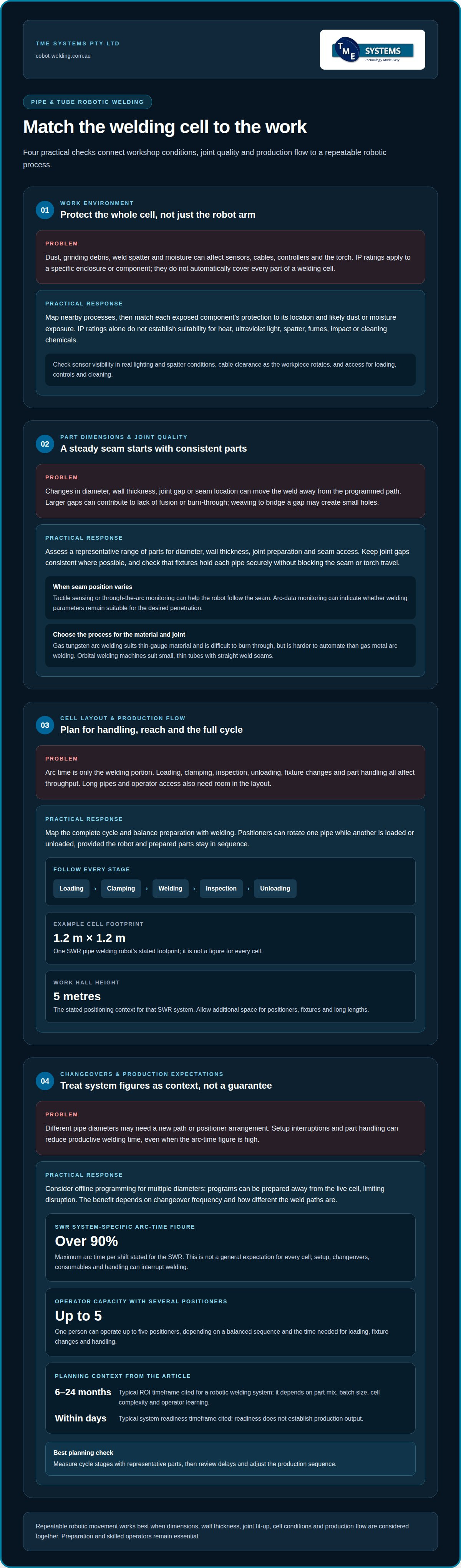
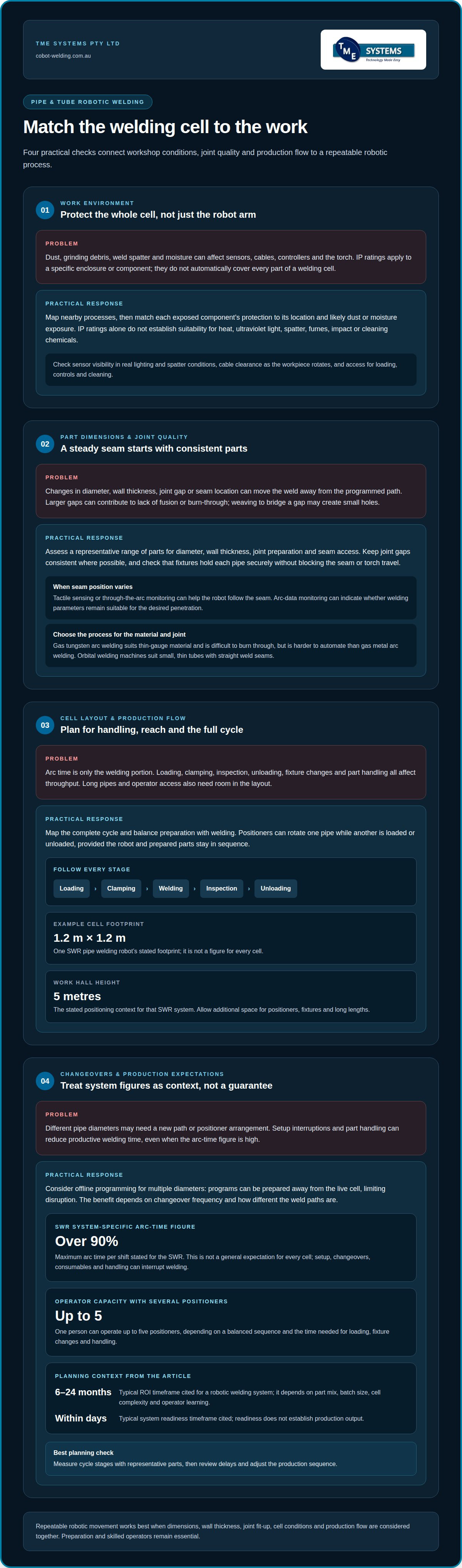
A welding cell’s surroundings affect its sensors, cables, controller and torch, not just the robot arm. Dust, grinding debris, weld spatter and moisture can interfere with equipment or increase cleaning and maintenance needs. A cell beside a grinding station, for example, faces different contamination risks from one in a clean assembly bay. Map nearby processes before choosing the cell’s location.
An IP rating describes an enclosure’s protection against solid objects and water. It applies to a specific enclosure or component, not automatically to every part of a welding cell. The robot, control cabinet, sensors and connectors may each have different protection requirements. Match each exposed component’s rating to its location and likely exposure to dust or moisture.
IP ratings don’t cover every workshop hazard. On their own, they don’t establish suitability for welding heat, ultraviolet light, spatter, fumes, impact or cleaning chemicals. A sensor facing the arc, for example, needs a clear view of the joint as well as protection from spatter. Its mounting position and protective measures must suit the welding process.
Allow room for the full work envelope, pipe loading and operator access. One SWR pipe welding robot has a stated footprint of 1.2 m by 1.2 m and can be positioned in a work hall with a height of 5 metres. These figures describe that system, not every pipe welding cell. Include positioners, fixtures and space to handle long lengths when planning the layout.
Before production, assess the work area and test the setup with representative parts. Check that sensors can track the seam in actual lighting and spatter conditions, and that cables stay clear as the workpiece rotates. Consider how operators will load parts, reach controls and clean the cell. These checks help match component protection to the environment.
Pipe dimensions and wall thickness
Pipe diameter and wall thickness affect more than robot reach. A small tube may need a different torch angle from a large pipe, while the joint must remain accessible around its circumference. The fixture and positioner must hold each diameter securely without blocking the seam or restricting torch travel.
Wall thickness affects the heat and travel settings needed to form a weld. Gas tungsten arc welding suits thin-gauge material and is difficult to burn through, but is harder to automate than gas metal arc welding. Orbital welding machines suit small, thin tubes with straight weld seams. The material and joint therefore help determine which approach fits.
Fit-up matters as much as nominal diameter. For robotic welding, keeping the joint gap consistent can help reduce weld defects. Larger gaps can lead to lack of fusion or burn-through. Weaving the torch to bridge a gap may also create small holes. Consistent joints give the robot a steadier path and help maintain the intended weld profile.
Dimensional accuracy supports repeatable positioning. If parts vary in diameter or joint location, the seam may shift away from the programmed path. Tactile sensing or through-the-arc monitoring can help a robot follow a seam when its location varies. Arc-data monitoring can also indicate whether welding parameters remain suitable for the desired penetration.
Assess a representative range of parts, not just one sample. Compare diameter, wall thickness, joint preparation and seam access across the production mix. Note where fixtures need adjustment or the torch needs a different approach. This helps show whether one setup can handle the work or whether distinct recipes and changeovers are needed.
For robotic welding for pipe and tube, dimensionally accurate parts and robot-friendly joints help keep weld locations within tolerance and minimise gaps. A consistent joint gives the robot a steadier target and makes programmed movement more repeatable. When thin tube, straight seams and varied joint fit-up all occur, consider their combined effect when selecting the process and cell setup.
Production planning and throughput
Throughput depends on the full cycle, not just arc time. Include loading, clamping, welding, inspection and unloading when estimating output. A short weld can still create a bottleneck if each pipe needs lengthy manual positioning. Mapping these tasks shows where the robot can save time and where operator attention remains essential.
Positioners can keep production moving by rotating one pipe while another is loaded or unloaded. With several positioners in use, one person can operate up to five. This arrangement depends on a balanced sequence: the robot must finish welding before the next prepared part is ready. Loading, fixture changes and part handling all affect the pace.
Arc time measures how long the robot spends welding, not total shift output. The SWR’s arc time can be maximised to over 90% per shift. Treat this as a system-specific figure, rather than a general expectation for every cell. Interruptions for setup, changeovers, consumables or part handling can reduce productive welding time.
Changing pipe diameters adds setup work when each new part needs a different path or positioner arrangement. Offline programming can reduce changeover time for production involving multiple diameters. It lets a program be prepared away from the live cell, limiting disruption while production continues. The benefit depends on how often parts change and how different their weld paths are.
Build the production case around part mix, batch size, cell complexity and operator learning. A typical robotic welding system can realise return on investment within six to 24 months, depending on those factors. A system can typically be ready for operation within days, but readiness doesn’t establish its output. Measure actual cycle stages with representative parts, then review delays and adjust the production sequence.
Pipe welding robot definition and operation
A pipe welding robot combines a programmed torch path with controlled movement of the pipe or torch. Its suitability depends on the joint, welding process and production task.
How robotic pipe welding works
A pipe welding robot moves a torch along a pipe joint. A positioner can rotate the pipe to keep the torch aligned with the weld. This supports repeatable passes on recurring parts, but joint variation can affect results. Large gaps can cause lack of fusion or burn-through, limiting automation when fit-up is inconsistent.
Unlike manual welding, robotic welding repeats programmed movements while an operator loads parts and oversees the process. Orbital machines suit small, thin tubes and straight weld seams. A robot cell can suit other production needs when its reach and setup match the work.
Welding processes for pipe and tube
Robotic pipe and tube fabrication can use gas metal arc welding (GMAW) or gas tungsten arc welding (GTAW). GMAW is generally easier to automate, while GTAW suits thin-gauge material and is difficult to burn through. The choice affects setup and process control, so assess the material, wall thickness and joint before selecting a process.
Some systems use a tool changer to switch between processes or wires. This can support varied jobs, but each change requires suitable settings and a programmed path.
Equipment in a robotic welding cell
A cell typically combines a robot, welding torch, power source, controller and fixtures, with a positioner where needed. Sensors can help track a seam, while arc-data monitoring can indicate whether parameters remain suitable for the desired penetration.
In Australia, applicable welding standards and work health and safety requirements depend on the job and cell design. Identify relevant requirements through the work specification and risk assessment, including controls for operator access, fumes and the welding arc.
System setup and programming steps
Setup starts by defining the pipe, joint, material and welding process. The system is then arranged to hold the work securely while providing torch access. An operator teaches or programs the path, then refines movement and welding parameters using representative parts.
Test welds show whether the path and settings suit the actual joint. Check the seam, penetration and repeatability before production. Operators also need training to load parts, run the cell and respond to process interruptions.
For a practical discussion about planning a robotic welding cell, consider how your pipe range, joint preparation and operator workflow fit together.
TME Systems: Collaborative Robot Welding Cells
TME Systems Pty Ltd helps Australian manufacturers assess pipe welding automation through collaborative robot welding cells and welding system integration. This is a practical next step when repeatable welds matter, but cell layout, part handling or operator workflow still need careful planning.
No-Code Teaching Software lets operators teach weld paths and adjust parameters without traditional programming. This helps your team refine the process around real production work. TME Systems’ Mobile Demo System can bring the technology into a practical discussion about your parts and workflow.
If you’re considering automation for pipe or tube welding, contact TME Systems Pty Ltd to discuss your production needs.
Turn production requirements into a practical next step
The key decision isn’t simply whether a robot can weld a pipe. It’s whether automation suits the parts, workflow and quality expectations your team handles day to day. Start by identifying repeat jobs, variations that cause delays, and where operators need flexibility. This gives you a practical basis for discussing a cell’s role in production.
Assess robotic welding for pipe and tube against real production work, not an idealised cycle. Consider how your team would teach paths, manage different jobs and build confidence operating the system. A useful discussion connects these practical needs with a suitable approach and keeps the people who will use the equipment in view.
To discuss how automation could fit your welding work, contact TME Systems Pty Ltd about robotic welding. A clear view of your production priorities is a good place to begin, and your team can take the next step at a pace that suits the work.
Frequently Asked Questions
What is a Pipe Welding Robot?
A pipe welding robot guides a welding torch along pipe or tube joints using a programmed path. The robot arm is only one part of the setup: fixtures, a positioner, a welding power source and controls can all affect the job. This matters when planning automation, because the complete cell must suit the parts and the way operators handle them.
What is robotic welding for pipe and tube, and how does it work?
Robotic welding for pipe and tube uses programmed torch movement to make repeatable welds on cylindrical workpieces. The pipe is secured, and the operator selects or teaches the required weld path. The system follows that path while the welding equipment supplies the arc. For a family of similar parts, saved paths and settings help operators repeat jobs and make adjustments without rebuilding each task from scratch.
What pipe and tube sizes, materials and joint types can welding robots handle?
Suitability depends on robot reach, the fixture and positioner arrangement, and the welding process. Material, wall thickness, joint geometry and torch access also influence whether a weld can be automated reliably. A production mix of short tubes and long pipe assemblies may need different handling arrangements. Assess part families together, including joint preparation and variation, rather than judging suitability by diameter alone.
What are the productivity and labour savings of robotic pipe welding?
Robotic welding can reduce the time operators spend guiding repeated welds, but loading parts, preparing joints and managing production remain necessary. Labour savings depend on how tasks are organised around the cell and how often suitable parts recur. An operator may shift from continuous torch handling to part handling and process oversight. Measure the full workflow, not arc time alone.