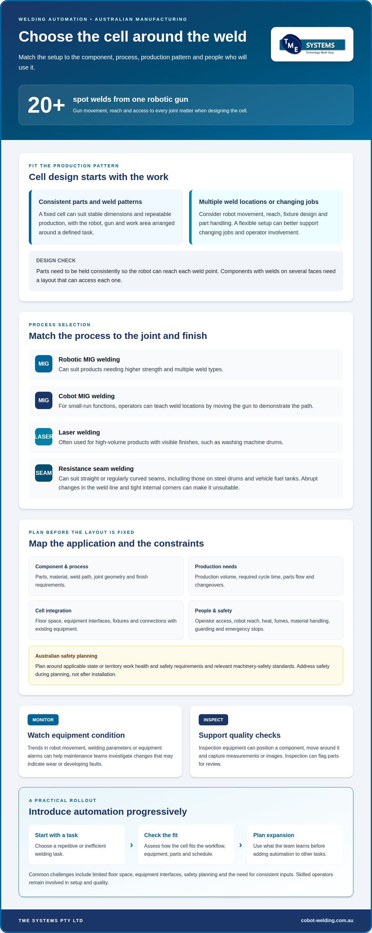

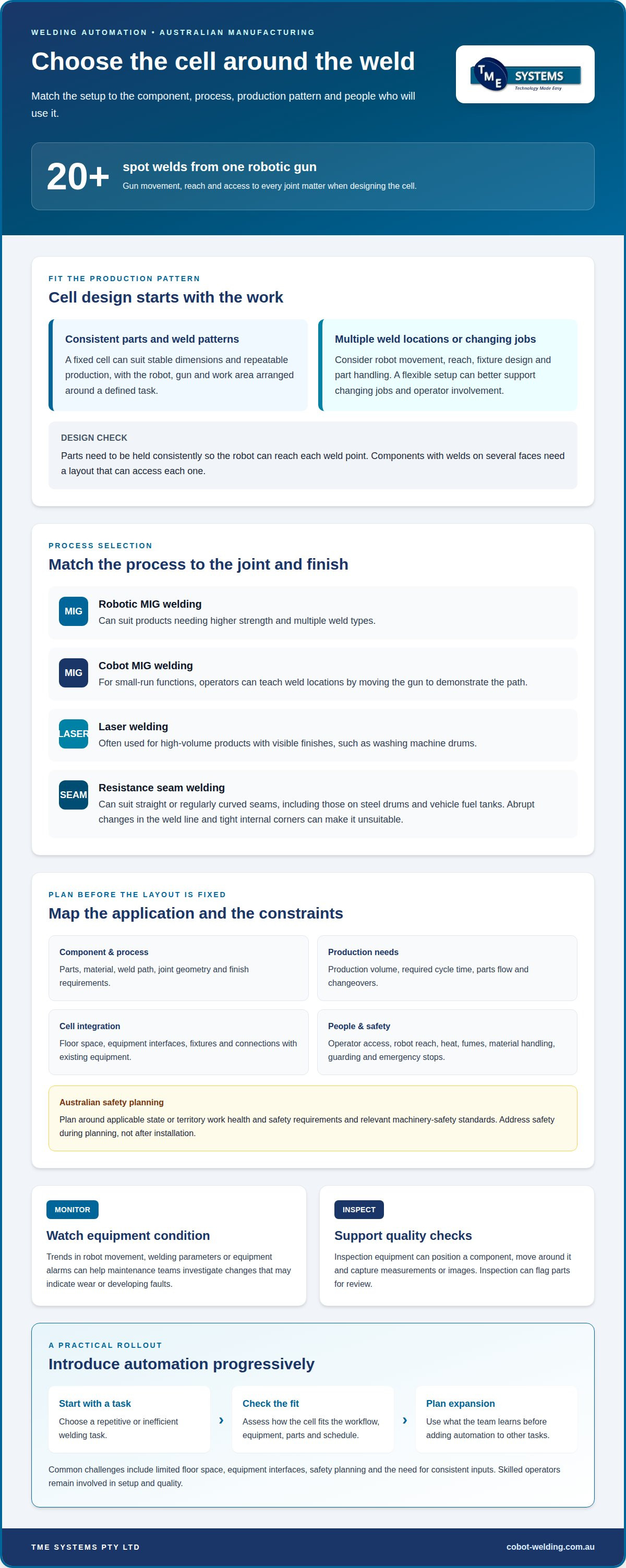
A single robotic spot-welding gun can perform more than 20 spot welds, but that doesn’t mean a fixed cell suits every production line. Smart factory solutions for welding should match the component, process, repeatability, workspace and required cycle time. A fixed cell may suit consistent production, while a more flexible setup can better support changing jobs and operator involvement.
Choosing smart factory solutions for welding means more than adding a robot. The cell needs to suit the parts, process and people using it, while helping the plant maintain weld quality and manage interruptions.
This guide explains how Australian manufacturers can assess welding automation, where process monitoring and quality inspection fit, and what to consider before automating a task. It also covers how collaborative robots can support welding while keeping operators involved in the transition.
Key Takeaways
- Match the welding cell to the production pattern: fixed setups favour stable, repeatable work, while robotic cells can support tasks that need more movement or flexibility.
- Use equipment condition data to spot changes that may signal maintenance needs, and pair it with weld inspection to help identify quality issues.
- Compare welding processes against the part’s material, weld path and finish requirements before deciding whether a robot or cobot is suitable.
- Consider how no-code teaching software and operator onboarding can help workers teach weld paths and adjust parameters as automation is introduced.
Automation considerations for Australian manufacturers
Plan welding automation around the component, welding process, production volume, workspace and required cycle time. These factors shape the cell layout, integration needs and quality checks.
Planning Automation Around the Application
Application-led planning matches the automation to the part, weld process and production task. Map the components, cycle time, floor space, equipment interfaces, safety requirements and production volume first. This reveals whether a cell can fit the current workflow and connect with existing equipment. It also highlights future expansion needs before the layout is fixed. For quality checks, inspection equipment can position a component, move around it and capture measurements or images.
Supporting Repeatable Production Runs
Automated welding is a strong candidate for repeatable work where parts and processes follow a consistent pattern. Stable production makes it easier to establish a repeatable weld path and cycle, while inspection can flag parts for review. Productivity depends on the task, parts flow and cell cycle time, not automation alone. Reassigning suitable lifting or work near fumes and heat may also reduce workers’ exposure to those tasks. Automation supports production, while skilled operators remain involved in setup and quality.
Introducing Automation Progressively
A staged approach adds automation to an existing operation one task at a time. Start with a repetitive or inefficient welding task, then assess how the cell fits the workflow before expanding. This gives the team a chance to learn how the equipment, parts and schedule interact. Common challenges include limited floor space, equipment interfaces, safety planning and the need for consistent inputs. Addressing them early helps avoid designing a cell around a workflow the factory cannot sustain.
Safety Standards and Regulations
In Australia, plan robotic welding around applicable state or territory work health and safety requirements and relevant machinery-safety standards. Assess the specific cell’s robot reach, welding heat, fumes, material handling, guarding, operator access and emergency stops. These factors affect layout and controls, so address them during planning rather than after installation.
Australian manufacturers considering grants or other support can compare their project scope with current federal and state or territory manufacturing programs. A welding integration project can involve defining the cell, equipment interfaces and implementation requirements. Eligibility and funding conditions vary by program, so use its published criteria when developing project assumptions.
Fixed and robotic spot-welding cells
Fixed and robotic spot-welding cells suit different production patterns, depending on part handling and weld positions. A robotic spot-welding gun can perform more than 20 spot welds, making its movement and reach important design considerations.
Robotic Spot-Welding Cells
A robotic spot-welding cell uses a programmed robot to position a welding gun at several points on a component. This can help manage parts requiring repeated welds in different locations. A single robotic spot-welding gun can perform more than 20 spot welds, so the sequence and access to each joint matter. The cell’s fixtures must hold components consistently, helping the robot reach each weld point. Reliable part positioning is central to repeatable results.
A fixed cell arranges the robot, welding gun and work area around a defined task. This can suit components with stable dimensions and a consistent weld pattern. Where weld locations vary, the setup may need to reposition the part or adapt the robot’s reach. For example, a component with welds on several faces needs a layout that can access each one. Part shape and handling requirements help determine the arrangement.
Comparing Robotic Welding Solutions
Robotic welding automates the movement and execution of a welding task; smart manufacturing connects production equipment with process information. The distinction matters: a robot can repeat a weld path, while connected controls and sensors can help monitor a broader cell. Compare options against the component, weld pattern, production volume, available space and equipment interfaces. These details clarify whether the priority is automating one task or coordinating several production stages.
For a dedicated spot-welding station, assess gun access, fixture design and component changeovers. For a connected cell, consider how the robot, sensors and controls exchange information. A well-matched collaborative robot welding cell may suit an application where operators need to teach small-run functions by guiding the MIG gun to demonstrate weld locations.
Automatable Welding Processes
Robots and cobots can support several welding processes, but each suits different joint and production requirements. Robotic MIG welding can suit products needing higher strength and multiple weld types. Cobots can also be taught small-run MIG functions by moving the gun to demonstrate weld locations. That hands-on teaching approach can help operators adapt the path for a particular part.
Laser welding is often used for high-volume products with visible finishes, such as washing machine drums. Resistance seam welding can suit straight or regularly curved seams, including those on steel drums and vehicle fuel tanks. Abrupt changes in the weld line and tight internal corners can make seam welding unsuitable. Comparing joint geometry and finish requirements helps narrow the process choice.
Predictive maintenance and quality assessment
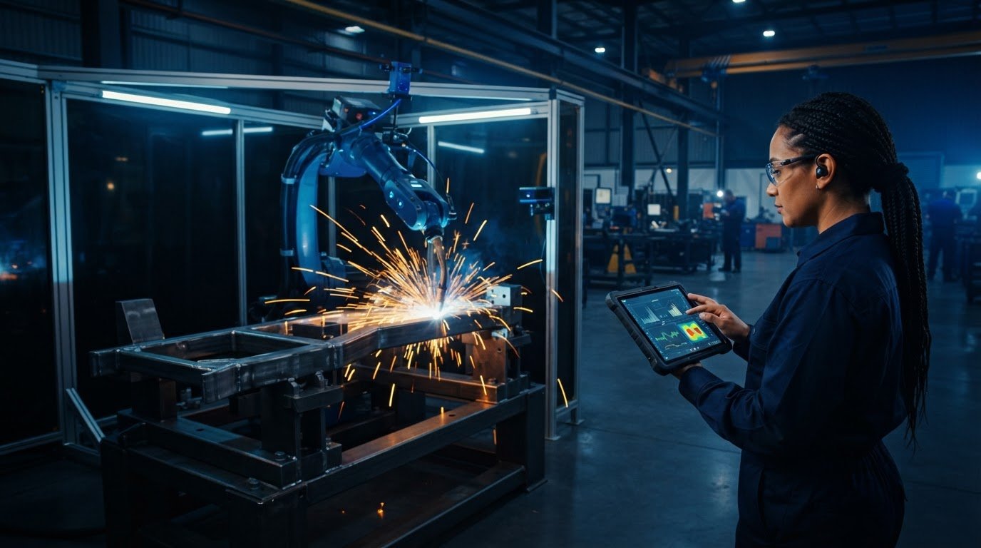
Predictive maintenance uses equipment-condition data to spot changes that may indicate wear or developing faults. In a welding cell, trends in robot movement, welding parameters or equipment alarms can help maintenance teams investigate before a fault interrupts production. Compare current readings with the cell’s normal operating pattern, then record the inspection or maintenance that follows.
One unusual reading does not identify its cause. A change in weld current, for example, could relate to the power source, consumables, material fit-up or process settings. Compare the reading with recent production records and inspect the relevant equipment or parts. This gives the team a basis for deciding whether to investigate maintenance, adjust parameters or carry out further quality checks.
Quality assessment combines process monitoring with inspection of completed welds. Robotic inspection equipment can position a component, move around it and capture measurements or images. These records can help locate variation across a part, while physical inspection assesses the weld against the job’s acceptance criteria. Choose inspection methods to suit the component, joint and required quality evidence.
Mechanical testing can also show why assessment must look beyond appearance. A gas tungsten arc welded 316 L stainless-steel joint had a reported yield strength of 329 MPa, compared with 308 MPa for the base plate. Its reported tensile strength was 630 MPa, compared with 603 MPa for the base plate. These figures are study results, not automatic acceptance limits for other components or welding jobs.
Make inspection findings useful by linking them to the part, weld location and production record. If images show a recurring issue at one joint, review the fixture, component position and weld path. If alarms repeatedly come before a stoppage, use that sequence to focus maintenance checks. This feedback helps operators and maintenance staff refine the process without treating every variation as the same fault.
Which welding processes can be automated with robots and cobots?
Robots and cobots can automate welding, but the right process depends on joint geometry, material, finish and production pattern. Match the process to the component to avoid designing a cell around a weld path the equipment cannot reach consistently.
MIG welding can join heavier-gauge materials with lap, fillet and butt welds. A robot can follow a programmed path for repeatable work; with a cobot, an operator can teach weld locations by guiding the MIG gun. Part position and access to each joint influence the cell layout.
Laser welding is often used for high-volume products where visible finish matters, including washing machine drums. Consider whether the required output, part presentation and weld locations suit a consistent automated process. Finish requirements should inform process selection, not just final inspection.
Resistance seam welding suits straight or regularly curved seams. Applications include steel drums, vehicle fuel tanks, tin cans and domestic radiators. The process is less suited to abrupt changes in the weld line or tight internal corners. Check these geometry limits before starting cell design.
Other processes bring different technical demands. Plasma welding applies temperatures of nearly 16,000 °C to very small areas, so heat concentration and the target joint are central considerations. TIG automation also depends on the specific material and setup: a study examined 6 mm-thick grade 2205 stainless steel, while IIoT-enabled TIG experiments used 1.5 mm SS304 sheet. These examples illustrate why process trials and application details matter.
Compare candidate processes against the weld profile, part material, access, finish and expected production consistency. Then assess whether the robot or cobot can reach the joint and maintain the required path. For a practical discussion of cobot welding applications, explore collaborative welding options.
TME Systems: No-Code Teaching Software
TME Systems provides No-Code Teaching Software that lets operators teach weld paths and adjust parameters without traditional programming. It can suit manufacturers who want to automate welding while keeping operators involved in setting up tasks. Collaborative Robot Welding Cells and integration services can connect a cobot setup with the production task and existing equipment. The Mobile Demo System brings a portable welding cell to a customer’s site for hands-on evaluation.
These options are most relevant when a repeatable welding task has been identified and the next decision is how operators will teach or run it. To discuss a welding automation application, contact TME Systems Pty Ltd.
Shape your next welding automation decision
To explore smart factory solutions for welding, start by defining the production task you want to improve. Consider what the operator needs to teach, which process information should be monitored and how a cell must fit the wider workflow. This gives your team a clear basis for discussing an automation concept that builds on workshop knowledge.
TME Systems offers No-Code Teaching Software for teaching weld paths and adjusting parameters, along with Collaborative Robot Welding Cells, integration services and a Mobile Demo System. These options help manufacturers assess how collaborative automation could fit a specific welding task and involve operators in the transition.
Bring your application and production priorities into the conversation. Discuss welding automation with TME Systems Pty Ltd and take a considered next step for your plant.
Frequently Asked Questions
What are smart factory solutions for welding?
Smart factory solutions for welding connect equipment, controls and inspection records so teams can coordinate production and respond to variation. A cell might combine a robot, sensors and a vision system, while inspection equipment captures images or measurements of a positioned part. Linking results to the relevant component and production record gives operators useful context for follow-up.
What sensors and software are used for real-time welding monitoring and quality control?
Real-time monitoring can capture process or equipment signals through sensors and controls, while vision systems or robotic inspection equipment record images and measurements. Software can organise those records by part or job, helping operators compare inspection results with production context. Choose the setup to answer the quality question: tracking a weld path differs from checking a finished component’s dimensions or visible surface.
How can an Australian manufacturer assess readiness and plan a smart welding implementation?
Assess readiness by selecting a candidate part family and checking repeatable fit-up, stable fixturing, torch access and enough repeat work. Then map the weld sequence, part handling, operator tasks, existing power source and available floor space. For an Australian site, include an application-specific safety assessment and define who reviews quality records and responds to faults. Start with a defined process, agree what evidence shows it works, then use lessons to guide expansion.