
Could a fixture that holds every part firmly still be the reason your welds vary? If parts shift, clamps block the torch or changeovers drag, even a well-taught robot can struggle to repeat a job. The best practices for automated welding fixtures start with a practical balance: locate each part consistently, leave the joint accessible and design the setup around the parts you actually produce.
That balance matters whether you’re automating a steady, high-volume run or handling a varied mix of jobs. This guide explains how fixture choices affect repeatability and robot access, then compares simple, dedicated and adjustable approaches against different production needs. You’ll also find a practical way to trial a fixture before putting it into production. Because a fixture is part of a wider welding cell, we’ll consider how the robot, workflow and operator fit together, including how no-code teaching can support job adjustments once fixture requirements are established.
Key Takeaways
- Use locating points and supports that help parts seat consistently through repeated loading.
- Plan clamp positions and fixture geometry around the torch’s route to every weld.
- Match dedicated, adjustable or modular fixtures to your part variety and changeover needs.
- Apply the best practices for automated welding fixtures by trialling representative parts, recording results and refining the setup before production.
- Consider the fixture alongside the welding cell, operator workflow and job-adjustment process.
Why automated welding fixtures determine repeatability and workflow
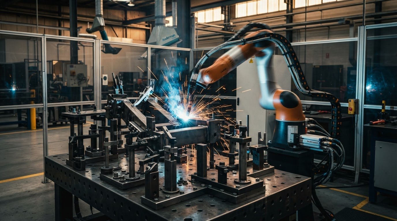
An automated welding fixture is tooling that locates and supports a workpiece while a robot performs a programmed weld. It presents the part in a known position so the robot’s programmed movements meet the intended joint. If the workpiece sits differently from cycle to cycle, the robot may follow the same path but meet the joint in a different position.
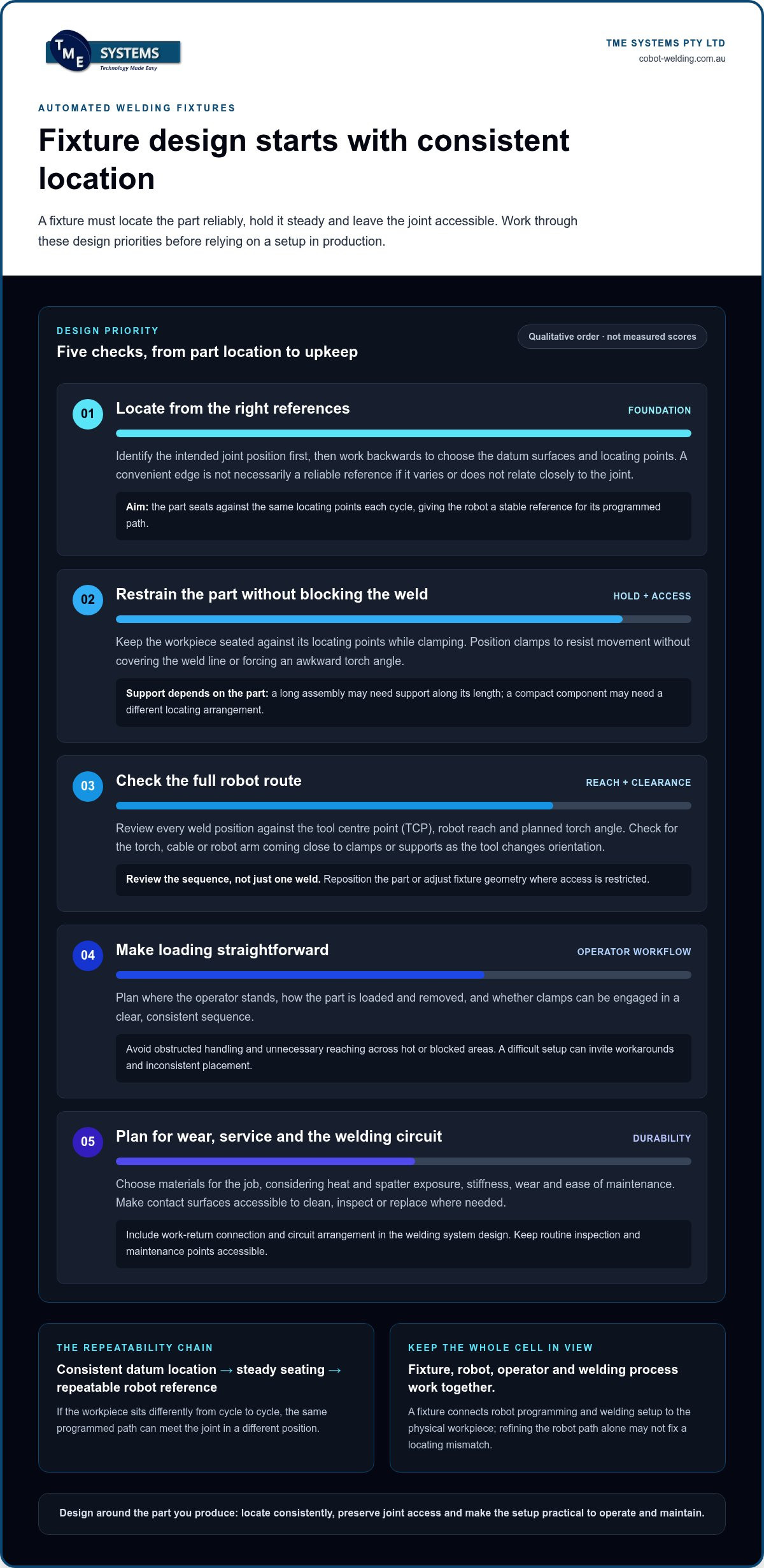
Consistent workpiece location gives a robot a stable reference for following a repeatable weld path. That’s why the best practices for automated welding fixtures start with how the part is located and held, not just how the robot moves. A general overview of robotic welding can help place fixturing within the broader process.
A fixture is one part of the setup, not a substitute for it. Robot programming defines the motion; cell selection concerns the wider equipment and layout; welding process setup addresses the parameters and procedure for making the weld. The fixture connects those decisions to the physical workpiece. If its locating arrangement doesn’t suit the part and joint, refining the robot path alone may not resolve the underlying mismatch.
What does an automated welding fixture need to control?
Start with the part’s datums: the reference surfaces or features used to establish its position. Locating points contact those references and constrain the workpiece so the joint lands where the programmed path expects it. Identify the intended joint position first, then work backwards to decide which surfaces the fixture should locate from. A convenient-looking edge isn’t necessarily a reliable datum if it varies or doesn’t relate closely to the joint.
Support and restraint matter too. The workpiece should stay seated against its intended locating points while it is clamped and welded. Movement can result from poor seating, an awkward loading sequence or restraint that doesn’t suit the part. Requirements depend on the part, joint and production task: a long assembly, for example, may need support along its length, while a compact component may need a different locating arrangement. There’s no universal fixture layout.
Where manual and automated fixturing differ
A skilled manual welder can adjust hand position and technique as the workpiece varies. A programmed robot follows its taught route, so it depends on the part being presented consistently. This shifts some repeat-positioning responsibility from the operator’s judgement to the fixture’s locating features. The operator still plays a vital role in loading parts correctly, checking seating and recognising when something doesn’t look right.
In practice, repeatable loading means each cycle begins from the intended reference points, with clamps applied in a clear, consistent sequence. A fixture that’s difficult to load can invite workarounds, such as placing a part differently to avoid an obstruction. Clear locating surfaces and a straightforward loading routine make the intended setup easier to follow. They support a dependable workflow, though the result still depends on the full welding process and how the cell is operated.
Design automated welding fixtures around location, access and durability
A fixture can hold a part firmly and still create problems if a clamp blocks a weld or the setup is hard to load. Design decisions work together: locating features establish position, clamps restrain the workpiece, and the fixture’s shape must leave room for the torch, operator and maintenance tasks. These are practical best practices for automated welding fixtures, but the right details depend on the part and welding task.
Start by mapping each joint and the path needed to reach it. Place datum surfaces and locating features to establish the workpiece position, then arrange clamps to resist movement without covering the joint or forcing an awkward torch angle. Check how an operator will load and unload the part as well. If the natural handling sequence is obstructed, the fixture may encourage inconsistent placement or unnecessary reaching.
Locate and clamp the workpiece without blocking the weld
Use locating features that seat against the part’s intended datum surfaces, rather than relying on a convenient edge that may not consistently relate to the joint. Place clamps to restrain the part without covering the weld line. Check the whole handling sequence: where the operator stands, how the part is removed and whether clamps can be engaged without reaching across hot or obstructed areas.
Plan robot reach, weld access and fixture life
Review every weld position against the robot’s tool centre point (TCP), reach and planned torch angle. A path that appears clear from one viewpoint may bring the torch, cable or robot arm close to a clamp or support at another orientation. Consider repositioning the part or adjusting fixture geometry where access is restricted, then review the full sequence rather than a single weld.
Choose materials with the job in mind. Heat and spatter exposure, required stiffness, wear and ease of maintenance all matter; no one material suits every fixture. Where contact surfaces are likely to wear or collect spatter, consider whether they can be cleaned, inspected or replaced without dismantling large sections of the setup. The American Welding Society provides foundational welding information that can help frame process-related design discussions.
Consider orientation, service access and the welding circuit in the same review. Plan how the work return connects to the workpiece, and include the circuit arrangement and other technical details in the welding system design. Keep routine inspection and maintenance points accessible, so upkeep doesn’t require awkward handling around the robot or fixture.
Design check: confirm part location, clear torch access, secure clamping and practical serviceability before finalising the fixture. TME Systems Pty Ltd collaborative robot welding cells bring fixture considerations into the wider cell discussion, alongside equipment and operator workflow.
Compare dedicated, adjustable and modular welding fixture approaches
The right fixture depends on the work mix, not on a universal rule. A stable part family made repeatedly may suit dedicated tooling; frequent changes between variants can favour adjustable or modular arrangements. Compare the options against part variety, repeatability, changeover frequency and how easily an operator can load and unload each part.
Dedicated: Suits a stable part family and repeated production task. Fixed locating features support consistent presentation, while changes between jobs may require a different fixture. Operator loading can be straightforward when the part and clamp sequence are designed around one job.
Adjustable: Suits related variants that need repositionable stops or clamps. It offers flexibility, but settings must be reset and checked at changeover. Clear references and a simple adjustment routine help operators return the fixture to the intended setup.
Modular: Suits varied work where reusable components can be rearranged for different parts. Changeovers involve configuring and checking the new layout, and the operator needs a clear loading method for each arrangement. Consistent locating depends on setting components against defined references.
Use this comparison as a starting point, then consider how often jobs change and how much variation exists within each part family. A fixture that accommodates more parts may need extra setup and verification. A dedicated design may simplify loading for its intended job, but require separate arrangements for other work. Include storage, inspection and maintenance in the decision: dedicated fixtures need a place to be kept between runs, while adjustable and modular components need organising so they remain available and in good condition.
When does a dedicated fixture make sense?
Dedicated tooling can suit a stable part family with a repeated production task. Its locating features are arranged for that work, rather than adjusted across unrelated jobs. The trade-off is reduced flexibility: a new variant may need changes or a separate fixture. Before choosing it, account for where the fixture will be stored, how its locating surfaces will be maintained and how operators will load the part.
When are adjustable or modular fixtures more practical?
Adjustable or modular approaches can suit short runs and varied work, particularly when parts share useful locating references. After each changeover, confirm that components are secure, references are restored and the robot’s weld access still works for the revised setup. A written setup record or clear component labels can help operators follow the intended arrangement. Flexibility alone doesn’t guarantee faster or more profitable production.
Fixture choice also needs to fit the wider automation workflow, including robot reach, loading and the jobs operators will teach or adjust. For context on how those decisions sit within a cell, see this guide to collaborative robot welding cells. This puts the best practices for automated welding fixtures in practical terms: match the tooling to the production mix, then verify each setup for the work it must handle.

Validate an automated welding fixture before relying on it in production
A fixture that looks right on the drawing still needs to work with real parts, real loading steps and the programmed weld path. A structured trial can reveal inconsistent seating, obstructed torch movement or awkward operator handling before the setup becomes part of routine production. These best practices for automated welding fixtures make the review observable and repeatable.
Work through the checks in sequence, recording what happens rather than relying on a quick visual impression:
- Define requirements. Note the part references, intended joint positions, clamp locations, weld sequence and expected loading method. Include the range of part variation the fixture is meant to handle.
- Check fit. Seat the workpiece against its intended locating points. Confirm that clamps engage as planned and the part doesn’t rock, bind or need to be forced into place.
- Trial representative parts. Use parts that reflect the job, including relevant variations, and follow normal loading and unloading steps. Observe the robot path at each weld position, checking torch clearance, clamp interference and access around the fixture.
- Record results. Capture seating observations, clamp positions, any contact or interference, spatter exposure and operator handling issues. Note which part and fixture configuration were used.
- Refine and repeat. Adjust the fixture or setup where the trial shows a problem, then repeat the relevant checks. Revisit the robot path if a fixture change affects access or the workpiece position.
Run a repeatability and accessibility trial
Repeat the load-and-seat cycle using the ordinary operator sequence. Check whether the part returns to the same locating points each time, and note any variation in seating or clamp position. Observe the torch route through the full weld sequence, not just at the first joint. Look for contact risks, spatter build-up in working areas and handling steps that make it difficult to position or remove the part consistently.
Document adjustments, safety and maintenance checks
Keep a practical setup record that identifies the part references, fixture settings, clamp positions and approved changes. Include what operators should inspect before running the job, such as loose components, worn surfaces, spatter on locating points or damage that could affect seating. Review operator handling and relevant risk controls as part of the trial. Confirm applicable Australian workplace and machinery requirements with the appropriate safety personnel; don’t assume a standard applies without checking its scope.
Fixture validation also connects to the robot’s taught path and the wider cell setup. TME Systems Pty Ltd supports welding system integration and operator onboarding, helping teams consider equipment, workflow and the operator’s role together. To discuss how a collaborative welding setup fits your production task, explore collaborative robot welding options.
Bring fixture design into a complete collaborative welding workflow
A fixture doesn’t operate in isolation. Its locating points, clamp positions and loading method need to work with the robot, welding equipment and the way jobs move through the production area. A fixture may suit the part on its own, yet cause delays if it doesn’t fit the cell layout, existing equipment or the operator’s normal handling sequence.
Bring those requirements into the integration discussion early. Consider which parts will be presented, how operators will load and unload them, which welds the robot needs to reach, and how the fixture fits alongside equipment already in use. TME Systems Pty Ltd supports welding system integration and operator onboarding, connecting fixture needs with the wider cell and day-to-day workflow. For broader planning considerations, see this guide to welding system integration.
Coordinate fixture requirements with integration and operator workflow
Share the fixture’s intended part references, loading sequence and weld access requirements as part of cell planning. This gives the integration discussion a practical basis for considering how the robot, existing equipment and operator tasks fit together. Onboarding helps operators understand how to use the cell and fixture as intended, including how to seat parts and follow the agreed setup. This keeps human know-how central to the automated workflow.
Make the design practical to teach, adjust and use
Clear locating features and repeatable loading provide a consistent starting point for teaching a weld path. If a job changes, operators may need to teach or adjust the path for the revised setup. No-code teaching software lets them teach weld paths without writing complex code. It doesn’t automatically compensate for a changed fixture or part position, so the setup and taught path still need to be considered together.
As you apply the best practices for automated welding fixtures, keep the hand-off between fixture design, integration and operator use clear. A practical review brings the part, fixture, weld access, equipment and loading routine into the same conversation. TME Systems Pty Ltd supplies and integrates collaborative robot welding cells, with operator onboarding to support teams as they put the workflow into practice.
Seeing an approach in context can make the discussion more concrete. Arrange a mobile welding robot demonstration to explore how collaborative welding could relate to your parts, fixture requirements and production workflow.
Take the next step towards a workable welding cell
The best practices for automated welding fixtures are most useful when tested against the parts, operators and production demands of your own workshop. Use your fixture requirements as a starting point for a broader conversation about how a collaborative welding cell could fit your workflow.
TME Systems Pty Ltd supplies and sets up collaborative robot welding cells, with welding system integration and operator onboarding to support their introduction into manufacturing environments. A mobile demonstration system offers a practical way to explore an automation approach in context.
Bring the parts and tasks you’re considering into that evaluation. A grounded discussion can connect fixture needs with the wider cell and the people who will use it. Arrange a mobile welding robot demonstration and take a considered next step towards automation that works with your team.
Frequently Asked Questions
Can an existing manual welding fixture be used for automated welding?
Sometimes, but an existing manual fixture needs a suitability review before it’s used in a robot cell. Check whether its locating surfaces position the part reliably, the clamps resist movement, and the torch can reach each joint without interference. Also review operator loading, work-return connections and cell interfaces. Trial the fixture with representative parts and review the complete setup before teaching or relying on a robot path.
How can a fixture accommodate variation between workpieces?
A fixture can manage a defined range of variation with adjustable locators, interchangeable contact pieces or separate settings for known variants. First identify which dimensions vary and which surfaces must remain the controlling references. For example, brackets of different lengths may share a datum edge but need repositionable end stops. Test the fixture at the variation limits. A robot path won’t automatically compensate for a part seated differently.
Should automated welding fixtures use manual or pneumatic clamps?
Neither type is automatically better; choose based on the job, operator routine and cell arrangement. Manual clamps may suit a straightforward setup, while pneumatic clamps may suit repeated actuation. Pneumatic options also add air supply and control considerations to the cell design. For either type, check that the clamp holds the workpiece without distorting it, keeps the joint accessible and supports consistent loading.
What is the TCP, and why does it matter when designing a welding fixture?
TCP means tool centre point, the reference point on the welding torch that the robot uses to position the tool. If the TCP is inaccurate, the programmed path may not place the torch where intended, even if the workpiece is correctly located. The fixture needs to allow the TCP to reach each joint at the required positions and angles. Recheck the TCP after torch or tooling changes, then verify the path.
How often should an automated welding fixture be inspected?
Set inspection frequency according to production use, exposure to heat and spatter, and the fixture’s maintenance needs. Include a visual and functional check before use, then schedule more detailed inspections as part of routine maintenance. Look for worn locating faces, loose hardware, clamp issues, spatter that affects seating and changes in the work-return connection. Record defects and actions taken so recurring issues can inform maintenance planning.
Can one fixture support more than one welding job?
Yes, if the jobs share compatible locating references and the fixture can be configured without compromising access or restraint. Related components may suit interchangeable stops, while unrelated parts may need separate tooling or settings. Treat each job as its own configuration: identify the part, confirm locator positions and clamps, and verify robot reach and path before production. The best practices for automated welding fixtures include validating each supported job, not assuming one setup suits them all.