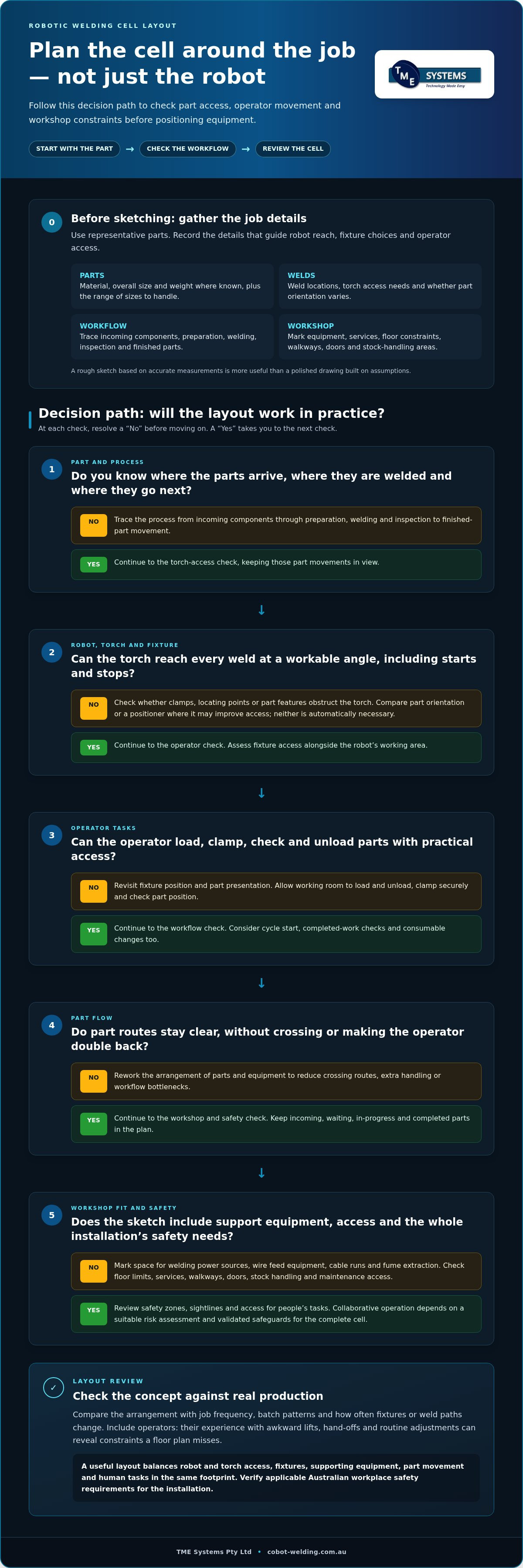

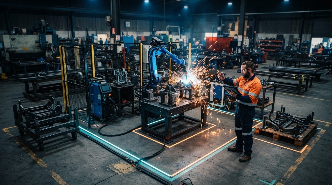
What if the best place for the robot isn’t the best place for the cell? Planning a robotic welding cell layout starts with the parts, weld access and operator movement, not simply the robot’s reach. A cell can fit neatly on a drawing and still make parts awkward to load, block access or disrupt the flow of work through your workshop.
Floor space matters, but the robot is only one part of the picture. Fixtures, welding equipment, incoming and finished parts, operator access and safe working practices all affect how the cell works day to day.
This guide will help you make those decisions before selecting or integrating equipment. Learn how to map part flow, assess operator tasks and workshop constraints, and plan an arrangement for the robot, welding gear and fixtures. We’ll also cover what to prepare for a cell planning discussion, so it can focus on your actual jobs and production needs. Involving operators from the outset and planning around existing workflows helps shape a cell around the way your workshop works.
Key Takeaways
- Start planning a robotic welding cell layout by mapping the job and part movement before positioning equipment.
- Consider robot reach, torch access, fixtures and operator movement together to make loading and welding practical.
- Compare compact and return-flow arrangements against your actual workshop footprint and production flow.
- Use a floor-plan sketch to map constraints, explore layout options and review risks before committing to a concept.
- Prepare part details, workflow information and operator tasks to guide integration and implementation planning.
Planning a robotic welding cell layout starts with the job, not the robot
A robotic welding cell layout is the planned arrangement of the robot, welding equipment, fixtures, parts and people around a welding task. Start with the work: understand how parts arrive, where they need to be welded and where they go next. Positioning the robot before mapping those movements can leave basic questions unresolved. Can the operator load the fixture comfortably? Will completed parts cross the route used for incoming components?
Planning early brings workflow constraints and integration decisions into view before equipment is positioned. It gives the team a clearer basis for discussing how a cell can fit existing equipment and routines. This section focuses on introducing a welding cell into an existing workshop, not redesigning the whole factory. For a general overview of the process and its applications, see Robot welding.
What information should you gather before sketching a cell?
Start with representative parts rather than trying to document every possible job. Record material types, overall part sizes and weights where known, weld locations, and the range of sizes the cell may need to handle. Note which joints need clear torch access and whether parts are presented in a consistent orientation or vary between jobs. These details help guide decisions about robot reach, fixtures and operator access.
Next, trace the current process from start to finish: incoming components, preparation, welding, inspection and movement of finished parts. Mark existing equipment, available services, floor constraints and areas that must remain accessible. Include walkways, doors and stock-handling areas. A rough sketch based on accurate measurements is more useful than a polished drawing built on assumptions.
Which production goals should guide the layout?
Decide what the cell needs to support most. Is the priority repeatable weld positioning, smoother part handling, throughput, operator ergonomics or a combination? The answer affects how you arrange loading, welding and unloading. For example, a layout that makes loading straightforward may be more suitable than one that simply places the robot close to the work.
Consider job frequency, batch patterns and how often fixtures or weld paths change. A cell planned around one frequent job may need a different arrangement from one handling varied work in smaller batches. Include operators in this discussion. Their experience with awkward lifts, hand-offs and routine adjustments can reveal constraints that are easy to miss on a floor plan.
Planning takeaway: A useful cell layout begins with the part, the welding process and the workflow requirements. These give the team a practical basis for comparing layout options.
Arrange the robot, welding equipment and operator around part flow
Once you understand the job, map how each part will be presented to the robot and moved through the cell. Robot reach matters only if the torch can approach each joint at a workable angle, including weld starts and stops. Fixture position and part orientation affect that access, so assess them alongside the robot’s working area rather than in isolation.
Trace incoming components, parts waiting to be welded, work in progress and completed parts. Look for routes that cross, make an operator double back or require extra handling. This flow-based approach is central to weld cell layout best practices: equipment placement should support the movement of work, not create bottlenecks.
How do fixtures and part presentation affect robot access?
A fixture holds the part in a repeatable position, but its clamps and locating points can limit the torch’s path. Check the approach to every weld, including whether nearby part features or fixture components obstruct the torch. Leave enough working room for the operator to load and unload parts, clamp them securely and check their position.
A positioner or a different part orientation may improve access to some joints, but neither is automatically necessary. Compare the actual weld locations, part shape and handling steps before deciding. The aim is to make the weld accessible while keeping loading practical.
How can the layout support the operator during production?
Place routine tasks where the operator can see and reach them without repeatedly walking around the cell. Consider where they’ll load parts, start a cycle, check completed work and change consumables. Allow practical access for setup, inspection and maintenance too. Welding power sources, wire feed equipment, cable runs and fume extraction all need space, and their placement affects visibility and access.
Consider safety across the whole installation. Plan appropriate safety zones, clear sightlines and access for the tasks people perform. A collaborative robot doesn’t, by itself, make every activity safe: collaborative operation depends on a suitable risk assessment and validated safeguards for the complete cell. Applicable Australian workplace safety requirements should be verified for the installation.
As you refine the drawing, check whether the operator can handle the part comfortably while keeping material routes clear. Planning a robotic welding cell layout means balancing robot and torch access, fixtures, supporting equipment, part movement and human tasks in the same footprint. If you’re exploring a concept around collaborative equipment, TME Systems’ collaborative robot welding cells provide a starting point for considering how integration can fit existing workshop workflows.
Compare robotic welding cell layouts against your parts and workshop
No single arrangement suits every job. Compare options against the parts you handle, how often they run and the space available in your workshop. A compact cell may keep equipment close, while separate loading and welding positions support a different work rhythm. Planning a robotic welding cell layout means weighing these practical trade-offs against actual material routes, not choosing a pattern by appearance alone.
| Layout pattern | Suitable conditions | Trade-offs | Questions to resolve |
|---|---|---|---|
| Compact, single-operator cell | Constrained floor space, shorter part routes and tasks one operator can manage. | Loading access, maintenance space and future adjustments may be harder to accommodate. | Can the operator load, unload and check parts without awkward movement? |
| Separate loading and welding positions | Work patterns where an operator can prepare or load one part while another is being welded. | Needs space for distinct task areas and a safe, workable way to move parts between them. | Do part volume and batch patterns support overlapping tasks? |
| Straight-through flow | A workshop footprint that allows parts to move forward from incoming to completed work. | The route may be impractical if the cell blocks existing production paths or access. | Can parts travel through without crossing other traffic? |
| Return-flow arrangement | A footprint where incoming and finished parts can be handled from nearby areas. | Shared routes may create congestion or extra handling if movements aren’t clearly organised. | Can incoming and completed parts be kept distinct? |
When might a compact cell suit the workflow?
A compact arrangement may suit a workshop with limited floor space, short material routes and a manageable sequence of operator tasks. A smaller footprint isn’t automatically a better fit, though. Check that there’s room to load and unload parts, access equipment for maintenance and make adjustments if the job mix changes. Cell dimensions depend on the selected equipment and application, so don’t assume a universal footprint.
When should you consider separating loading and welding tasks?
Separate loading and welding positions may let an operator prepare the next part while the robot welds, where the process and safeguards allow that workflow. Compare part volume, batch patterns, handling needs and safe access before choosing this arrangement. A positioner can change how a part is presented and which welds the robot can reach, but it also adds equipment and affects the space plan. For broader context on cell selection, read this guide to collaborative robot welding cells.
Test straight-through and return-flow routes against your actual floor plan. Mark where parts enter, wait, move for welding and leave. This comparison can reveal whether a layout supports production flow or creates a pinch point.
Plan a robotic welding cell layout in five practical steps
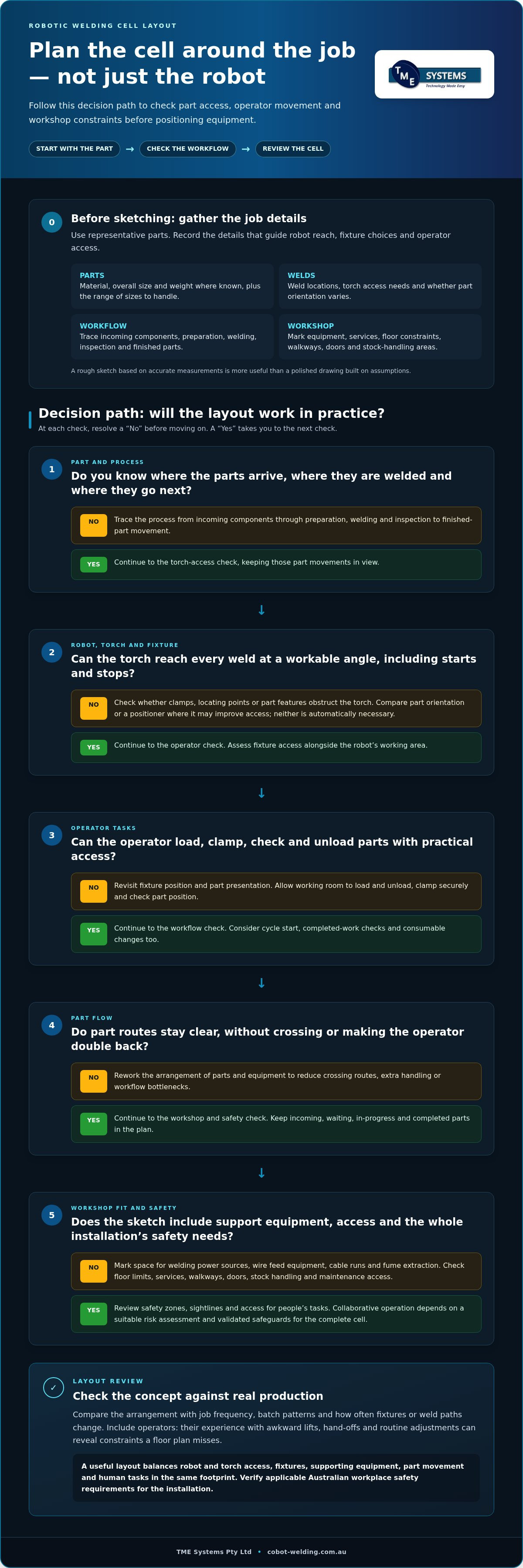
Turn the production details you’ve gathered into a draft that operators and the integration team can review. Keep it simple: the aim is to expose gaps and test the workflow, not produce a final engineering drawing. When planning a robotic welding cell layout, label assumptions separately from confirmed measurements so project decisions are based on what’s known.
- Map the process. Record the sequence from incoming parts through preparation, loading, welding, inspection and finished-part movement. Note who handles each step and where work waits.
- Measure constraints. Sketch the available floor area and mark existing equipment, access routes and fixed obstructions. Distinguish measured dimensions from estimates that still need checking.
- Sketch alternatives. Draw more than one arrangement. Show the robot’s working area, operator position, fixtures, welding equipment and incoming, in-process and completed-part routes.
- Review risks and interfaces. Consider operator movement, visibility, access for maintenance and how the proposed cell may interact with existing equipment and workshop workflows. Record safety questions for project review.
- Validate the concept. Walk through the proposed sequence with representative parts and fixtures. Capture what works, what needs adjustment and which assumptions need confirmation before implementation.
A floor-plan sketch needn’t be elaborate. Use a clear scale where measurements are available, label equipment and work areas, and use arrows to show part routes. Mark robot reach as a planning area, not proof that every weld is accessible. Keep a separate list of unknown dimensions, service requirements and integration questions instead of treating estimates as facts.
How do you test a draft layout before installation?
Walk through loading, clamping, teaching, welding, inspection and unloading in the proposed order. Use representative parts and fixtures to check whether the robot can reach the welds and whether the operator has practical access to each task. Record unresolved service, safety and integration questions for project review rather than assuming the sketch has answered them.
Which workflow and safety details need a closer review?
Review operator movement, sightlines, material handling and maintenance access across the complete arrangement. The integration team can assess how the cell interfaces with existing welding equipment and workshop routines. Consider applicable safety requirements for the installation as well. For the wider process, see this guide to welding system integration planning.
Planning meeting checklist:
- Representative parts, weld locations and fixtures are available for review.
- Part routes and operator tasks are marked on the sketch.
- Confirmed dimensions are distinguished from assumptions.
- Unresolved access, safety, service and integration questions are recorded.
Ready to turn a draft into an implementation discussion? Explore collaborative robot welding cell options.
Turn the layout concept into an integrated cobot welding cell
A workable layout is the starting point for integration, not the finished plan. It gives the team a basis for discussing how the collaborative robot, welding equipment, fixtures and existing workshop processes will work together. Those decisions also shape operator tasks and preparation before commissioning, from how parts are presented to how the cell fits established material movement.
TME Systems supplies collaborative robot welding cells and integrates robotic welding technology with existing equipment and workflows. Use your layout concept to work through equipment interfaces, operator responsibilities and the steps needed to bring the cell into production. Dimensions, equipment choices and production outcomes depend on the application, so document assumptions and open questions rather than treating an early sketch as a final specification.
What should the team resolve before implementation?
Bring the practical details into one review. Align representative parts and the welding process with the proposed fixtures, equipment interfaces and operator tasks. Agree how the team will assess whether the cell concept suits the job, and record unanswered questions about the layout or its connection to existing workflows. This gives the integration discussion a clear foundation and makes project decisions easier to follow.
Commissioning preparation should account for how operators will use the cell, including setup, routine tasks and adjustments. If weld paths change between jobs, consider how those changes will be taught and managed as part of the operating process.
How can operators become part of the cell transition?
Operators understand handling realities that a floor plan can miss. Involve them in workflow reviews so they can comment on part presentation, clamping, visibility and practical access. Their input can also guide training and onboarding as staff learn to operate and maintain the cobot system.
No-code teaching software lets operators teach weld paths without writing complex code. This can help when jobs or paths need adjustment over time, while keeping the operator involved in how the cell is used. The layout and teaching approach should support the actual tasks people will carry out, rather than assuming every job follows the same routine.
For broader context, read about cobot welding productivity. To explore the equipment side of your concept, explore collaborative robot welding cells and discuss how a layout could fit your parts, operators and workshop workflow.
Build your next steps around the way your workshop works
Planning a robotic welding cell layout starts with the parts and the work around them. Map material movement, operator tasks and workshop constraints before settling on an equipment arrangement. Compare options against real jobs, and keep assumptions distinct from confirmed measurements as you prepare for integration.
A practical cell brings the robot, welding equipment, fixtures and operator tasks together. TME Systems supplies collaborative robot welding cells and provides integration and operator onboarding to connect the equipment with existing workflows. No-code teaching software lets operators teach weld paths without complex code, supporting adjustments as jobs change. A mobile demonstration system can also help explore a practical application.
Have a draft floor plan, representative parts and workflow notes ready for the next discussion. Discuss a practical cobot welding cell layout with TME Systems and take the next step towards a cell concept shaped around your workshop. Involving operators from the start helps ensure the planned cell reflects the work they know best.
Frequently Asked Questions
How much space do you need for a robotic welding cell?
There’s no fixed footprint for a robotic welding cell; the space depends on the equipment, parts and workflow. Include the robot, welding gear, fixtures, operator tasks and routes for incoming and finished parts. Allow room for loading, unloading, maintenance access and appropriate safety measures. Start with a site plan and representative parts, then review the proposed arrangement before settling equipment positions or dimensions.
What should be included in a robotic welding cell layout?
A layout should show the robot and torch, welding power source, wire feed equipment, fixtures, parts and operator work area. Also map fume extraction, cables, services, maintenance access, safety measures and material routes. The exact arrangement depends on the parts, welding process and workshop. A floor-plan sketch showing equipment and movement can help identify access or workflow conflicts before the final arrangement is decided.
Can a cobot welding cell fit into an existing workshop?
A cobot cell may fit an existing workshop if the available space, equipment, part flow and operator tasks can support it. Map the current process and measure the intended work area, including access and maintenance space. Consider how the cell will connect with existing equipment and services, and how parts will move through production. Integration planning helps align the proposed cell with established workshop workflows before positions are finalised.
How do you plan material flow around a robotic welding cell?
Trace components from arrival to the fixture, through welding, then to inspection or the next operation. Mark where parts wait and how operators handle them. Look for crossing routes, blocked access and repeated lifting or movement. Compare possible arrangements against actual parts and batch patterns. Include loading and unloading tasks in the flow map so it reflects the work happening around the cell.
Does a robotic welding cell need a welding positioner?
No, a positioner isn’t required for every application. It can change how a part is presented and may help the robot access different welds, but it also affects equipment placement, footprint and part handling. Review representative parts, weld locations and the welding process to see whether a positioner supports the task. Include it in the layout discussion if needed, rather than assuming it belongs in every cell.
How do you account for safety when planning a cobot welding cell?
Include safety in the layout from the outset and assess the complete application, not just the robot. Review operator movement, visibility, access, equipment interfaces and hazards associated with the task. Collaborative operation doesn’t remove the need for a suitable risk assessment or validated safeguards. Requirements depend on the installation and jurisdiction, so verify current Australian workplace obligations and any applicable standards as part of project planning.
When should you involve a welding system integrator in layout planning?
Bring an integrator into the discussion when the proposed cell needs to connect with existing welding equipment, production workflows or operator tasks. Early planning can help identify interfaces and unresolved assumptions while the layout is still being developed. Prepare representative parts, process steps, workshop constraints and production goals. TME Systems provides welding system integration and operator onboarding for collaborative welding solutions, helping connect cell planning with day-to-day use.
Can operators adjust robotic weld paths without coding?
Yes, no-code teaching software can let operators teach weld paths without writing complex code. The workflow depends on the software, robot and welding application. During layout planning, allow for where operators will teach and review jobs, and how they’ll access the cell for these tasks. Including path teaching in the workflow ensures the operator’s role is considered alongside loading, welding, inspection and other routine work.