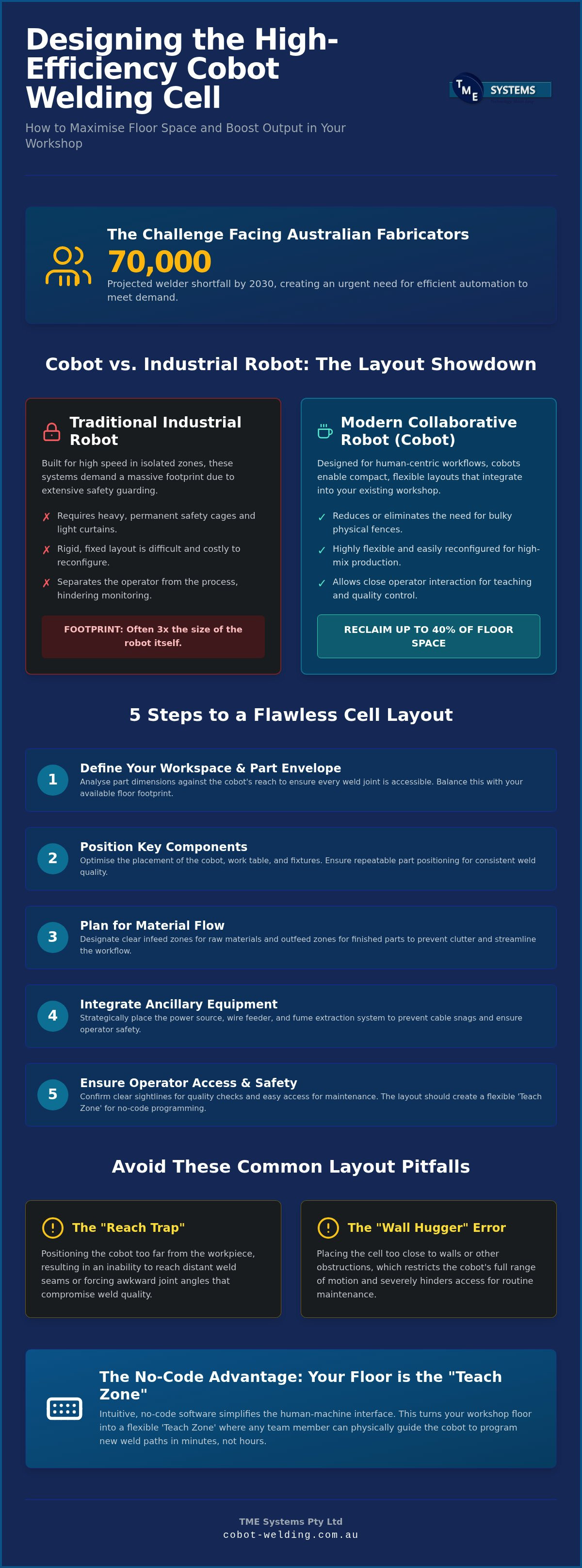

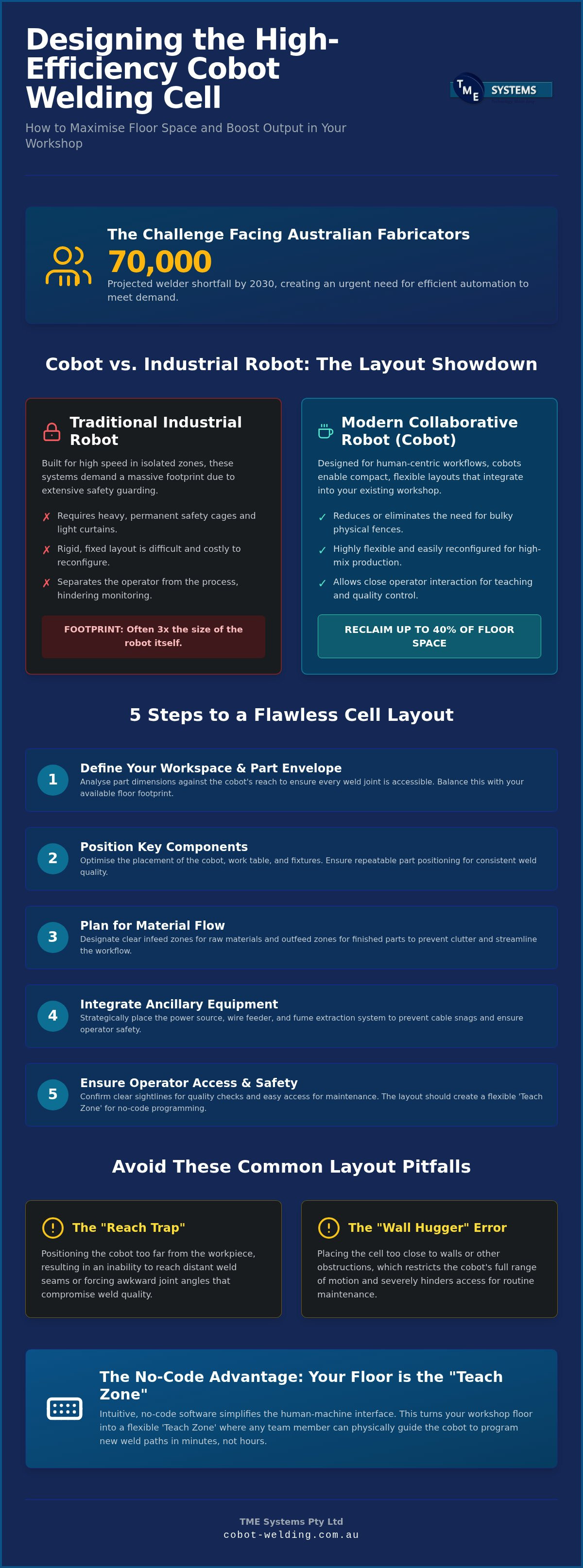
With Australia facing a projected shortfall of 70,000 welders by 2030, how can your workshop keep up with demand without doubling your floor space or your overheads? It's a question many local fabricators are asking as they try to balance growing order books with a shrinking labour pool. You likely know the frustration of wanting to automate but feeling held back by the massive footprint of traditional safety cages and the high cost of hiring specialist programmers. It's a common hurdle when you're trying to squeeze more productivity out of a workshop that's already at capacity.
This guide shows you how to design a high-efficiency welding robot cell layout that maximises every square metre of your floor and boosts output using modern cobot technology. You'll learn how to create a flexible welding cell that handles various parts and achieves better consistency without the massive overheads of old-school robotics. We'll explore how to move away from rigid, fenced-off zones toward human-centric layouts that use no-code teaching software to make automation accessible, safer, and far more adaptable to your daily workshop workflow.
Key Takeaways
- Balance robot reach with your floor footprint to ensure your system fits the unique constraints of your workshop without compromising on part size.
- Discover how collaborative robots allow for a more compact welding robot cell layout by reducing the need for traditional, heavy safety fencing.
- Master a five-step design process to define your part envelope and ensure the welding torch can access every joint with precision and consistency.
- Identify and avoid common setup mistakes, such as the "Reach Trap" and the "Wall Hugger" error, that often hinder routine maintenance and safety.
- Learn how no-code software simplifies the interface between operator and machine, turning your floor into a flexible "Teach Zone" for rapid reconfiguration.
Understanding the Foundations of an Efficient Welding Robot Cell Layout
A successful welding robot cell layout is far more than just a robot arm bolted to a concrete floor. It's a carefully synchronised system where the arm, the power source, and the operator work together. While Robot welding was once the domain of massive car plants, the reality for most Australian workshops is high-mix, low-volume production. This means a rigid, "standard" layout often fails because it doesn't allow for the quick changeovers and varied part sizes that local fabricators handle every day.
Your layout must balance the robot's maximum reach against the actual workpiece size and your available floor space. If the robot is positioned too far from the job, it'll struggle to hit the far seams. If it's too close, you risk axis limits or physical collisions. You also need to consider the placement of the welding power source and wire feeder. These aren't just accessories; they dictate the path of the torch leads. Poor placement leads to wire feeding friction or cable snags, which can quickly ruin a production run.
Key Components of a Modern Welding Cell
Every efficient cell starts with a stable mounting base. While fixed bases are common, many Australian shops now opt for mobile systems that can be moved with a pallet jack. This flexibility is vital when floor space is at a premium. Cable management is equally important. You need to organise the torch leads to ensure they don't catch on the robot or the fixtures during complex rotations. Finally, your workholding must be repeatable. If your fixtures don't hold the part in the exact same spot every time, the robot's precision is wasted.
The Impact of Material Flow
Think about how parts move through your shop. A well-designed welding robot cell layout includes dedicated infeed zones for raw materials and outfeed zones for finished work. This prevents clutter and reduces the distance operators have to travel. Safety is also a major factor in layout planning. With the Australian workplace exposure limit for welding fumes recently reduced to 1 mg/m³, your cell must be positioned to work with effective fume extraction. Whether you use a fixed hood or an integrated extraction arm, ensuring clean air for your team is a critical part of the design process, not an afterthought.
Cobot vs Industrial Robot: How Layout Requirements Differ
Choosing between a traditional industrial arm and a collaborative robot (cobot) is the single biggest factor in determining your final welding robot cell layout. Traditional industrial robots are built for high speed and heavy payloads, which means they are inherently dangerous to be around. To comply with strict safety standards like the AWS D16.1 Safety Specification, these machines must be housed behind heavy guarding, interlocked gates, and light curtains. This often triples the actual footprint of the robot itself, making it a difficult fit for many Australian workshops with limited floor space.
Cobots take a different approach. By using internal force-sensing technology, they can detect a collision and stop instantly. This allows for a much more compact layout where the robot can work in the same vicinity as your team. However, it's a mistake to think cobots never need guarding. While the arm is safe, the welding arc, intense light, and hot spatter still require protection for bystanders. The real advantage lies in the flexibility; because you aren't bolting massive cages to the slab, you can reconfigure your cell as your production needs change.
Space Savings with Collaborative Technology
By eliminating bulky safety cages, you can often reclaim up to 40% of the floor space required by a traditional system. Instead of physical fences, many modern layouts use area scanners that slow or stop the robot only when someone enters the immediate work zone. This makes the cell feel like a part of the workshop rather than an isolated island. If you want to dive deeper into how these systems function in a local context, our post on collaborative robot welding cells offers a detailed breakdown of the technology.
Operator Proximity and Interaction
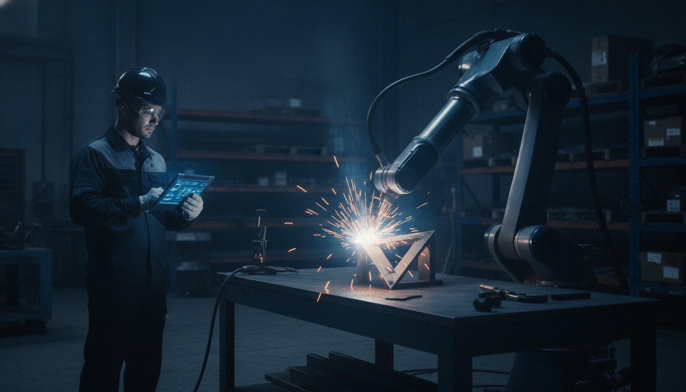
Designing for proximity means your operator can stay close to the action. This is vital for hand-guiding and path teaching, where a welder physically moves the arm to define the weld track. Clear sightlines are essential here. You want your staff to be able to monitor the weld quality without having to peer through layers of mesh or plexiglass. This side-by-side interaction turns the robot into a tool that supports the welder's skill rather than a distant machine that replaces it. If you're looking to see how this fits into your own shop, you can explore our range of integrated welding solutions.
5 Steps to Design Your Welding Robot Cell Layout
Designing a welding robot cell layout doesn't have to be a dark art. It's a methodical process that starts with your parts and ends with your people. While massive industrial plants have teams of engineers for this, Australian workshops can achieve the same precision by following five practical steps. This approach ensures your automation investment actually fits your workflow instead of forcing you to work around the machine.
- Step 1: Define the Part Envelope. Start by identifying the largest item you intend to weld. This "part envelope" dictates the minimum volume the robot must navigate.
- Step 2: Determine Reach and Stroke. Ensure the robot can hit every joint. Remember to account for the length of the welding torch, as this adds significant reach beyond the robot's faceplate.
- Step 3: Plan the Workholding. Decide if a fixed table is enough or if you need a rotary positioner. Positioners are vital for complex geometries where the robot needs to weld in a "down-hand" position.
- Step 4: Integrate Safety and Services. Map out where power, gas, and fume extraction will sit. These should be close enough to be efficient but far enough to avoid hindering movement.
- Step 5: Validate the Workflow. Walk through the operator's movements. How do they load parts? Where do they stand during the weld? Simulating this prevents bottlenecks later.
Optimising the Working Envelope
Every robot has a "Dead Zone," which is the area directly beneath or behind its base that it simply cannot reach. When planning your welding robot cell layout, you must position your workholding outside this zone. Using 3D simulation software is a great way to check for torch interference before you drill a single hole in your floor. If you're dealing with long or awkward parts, workpiece positioners become essential. They rotate the part so the robot always has the best angle, preventing the arm from hitting its axis limits or the part itself.
Utilities and Fume Management
In Australia, the workplace exposure limit for welding fumes has been slashed from 5 mg/m³ to 1 mg/m³. This means your layout must prioritise fume extraction. Position your extraction hoods or source-capture arms so they don't interfere with the robot's path but still pull air effectively away from the operator. Routing your gas and power lines is also critical. Keep them off the floor to prevent tripping hazards and use overhead booms or cable tracks where possible. This keeps the area tidy and ensures easy access for routine maintenance like wire spool changes or tip replacements.
Common Layout Mistakes and How to Avoid Them
Even the most advanced technology can't compensate for a poorly planned floor. Many Australian fabricators fall into the "Reach Trap" during their first setup. This happens when you calculate your welding robot cell layout based solely on the robot's arm length while forgetting that the welding torch and its mounting bracket add significant length. This oversight often leads to the robot reaching its axis limits prematurely or, worse, colliding with the very part it's meant to weld. Always factor in the torch geometry when mapping out your working volume.
Another frequent error is the "Wall Hugger" mistake. In an effort to save space, it's tempting to tuck the robot base into a corner or tight against a wall. However, this makes routine maintenance and cleaning nearly impossible. Spatter builds up and cables need inspection; if your team can't comfortably access all sides of the machine, these tasks get ignored. You should also consider your lighting. While the robot follows a programmed path, your operator needs clear, shadow-free visibility to inspect the weld pool and ensure the gas coverage is correct. Poorly placed overhead lights can cast deep shadows that hide defects until the part reaches the finishing stage.
Ergonomics for the Human Operator
Your layout must serve the person as much as the machine. Place the control pendant at chest height to prevent neck strain during long shifts. Ensure the operator's interface screen is angled to avoid glare from workshop lights. A common ergonomic failure is forcing staff to reach over recently welded, hot components to load the next jig. By designing the cell so that loading and unloading zones are easily accessible, you reduce the risk of burns and physical fatigue. This is especially important when handling heavy jigs that require a crane or pallet jack for positioning.
Future-Proofing Your Layout
Don't design for today's volume alone. Leave "expansion gaps" in your floor plan to accommodate a second robot or a larger rotary table down the track. Using modular T-slot tables or flexible flooring systems allows you to bolt down new fixtures or reconfigure the entire cell in a single afternoon. It's often helpful to consult with welding system integration specialists during the early planning phase to ensure your utilities and floor capacity can handle future upgrades. If you're ready to start planning your shop's transition to automation, you can book an on-site demonstration to see how these systems fit into your specific space.
Integrating No-Code Software into Your Layout Strategy
The software you choose has a direct impact on the physical welding robot cell layout of your workshop. In the past, robotic systems required a dedicated programming station, often a computer terminal located safely away from the robot's work zone. No-code software removes this barrier by allowing the operator to interact with the robot directly at the torch head. This shift means your layout doesn't need to accommodate a remote "programming office" but instead requires a functional "Teach Zone" where the welder and the machine can work in tandem.
By using no-code teaching software, you can drastically reduce the downtime associated with changeovers. In a traditional setup, changing a part might take hours of code adjustment; with a no-code system, it takes minutes. This speed allows for a more dynamic floor plan where the cell can handle a wider variety of jobs throughout a single shift. For small Australian shops, this flexibility is the key to making automation viable, as it ensures the robot remains productive even when batch sizes are small and part designs change frequently.
The Hand-Guiding Teaching Space
A layout designed for no-code software must prioritise accessibility. Because the operator teaches the robot by physically moving the arm, you need to clear any obstacles that might hinder their movement. This means ensuring the robot base is accessible from multiple sides, allowing the welder to reach every joint and seam without straining or tripping over cables. You can read more about how this technology works in our guide to no-code robot welding software, which explores the interface between the human welder and the machine.
Turnkey Cells: The Fast Track to Automation
For many fabricators, the easiest way to ensure a perfect welding robot cell layout is to opt for a turnkey collaborative unit. These systems are pre-designed with an optimised footprint, integrated fume extraction, and the no-code software already installed. They take the guesswork out of the setup process and allow for rapid deployment. If you're unsure how a unit will fit into your existing workflow, booking a mobile welding robot demonstration can help you visualise the layout in your own shop before you commit. Before your system arrives, use this final checklist for a successful deployment:
- Power and Air: Ensure 3-phase power and clean, dry compressed air are available at the installation site.
- Floor Stability: Confirm the concrete slab is level and thick enough to support the robot's dynamic loads.
- Extraction: Verify that your fume extraction system meets the new 1 mg/m³ Australian workplace exposure limit.
- Operator Zone: Clear a 1.5-metre radius around the worktable to allow for safe hand-guiding and part loading.
Future-Proofing Your Workshop Floor
Designing an efficient welding robot cell layout is no longer about building a permanent cage around a machine. It's about creating a workspace where human skill and automation complement each other perfectly. We've explored how collaborative technology removes the need for bulky fencing, allowing you to reclaim valuable floor space while maintaining high safety standards. By shifting to no-code software, you turn complex programming into a simple, hands-on task that your experienced welders can master in hours, not weeks.
TME Systems Pty Ltd provides pragmatic advice from local Australian integration experts who understand the realities of a busy production line. Our turnkey solutions are designed to fit your existing floor plan, ensuring you get the benefits of improved consistency without massive overheads. If you're ready to see how this technology works in your own environment, Book a Mobile Demo to See Your Perfect Layout in Action. Taking this step helps demystify the transition to automation and sets your workshop up for steady, long-term success.
Frequently Asked Questions
How much floor space does a typical welding robot cell require?
A typical collaborative welding robot cell layout requires a footprint of approximately 2.5 metres by 2.5 metres, depending on your workpiece size. This is significantly smaller than traditional industrial systems, which often demand 4 metres by 4 metres or more to account for safety fencing. Because cobots use force-sensing technology to work safely near humans, you can reclaim valuable workshop floor space that would otherwise be lost to rigid steel cages.
Can I move my welding robot cell once it is installed?
Yes, many modern collaborative units are designed for mobility and can be moved using a standard pallet jack or forklift. Unlike traditional robots that are permanently bolted to a dedicated section of the slab, these mobile systems allow you to reconfigure your workshop floor as production demands change. This flexibility is ideal for Australian fabricators who need to move the robot between different workbenches or storage areas throughout the work week.
Do I need a special foundation or floor for a welding robot?
Most collaborative welding robots don't require a specialised foundation and can be installed on a standard 100mm to 150mm level concrete workshop floor. The key requirement is that the surface is level and stable enough to prevent any vibration during the weld cycle. While heavy industrial robots with high-speed movements might need reinforced slabs, a typical cobot system is lightweight enough to sit on existing workshop surfaces without extra structural work.
What is the most common mistake in welding cell design?
The most common mistake is failing to account for the physical length of the welding torch when mapping out the robot's reach. This "Reach Trap" often leads to the robot hitting its axis limits before it can finish a seam. Another frequent error is placing the robot too close to a wall, which blocks access for routine maintenance. Always ensure there's enough room for a technician to clean the system and change wire spools comfortably.
How does a cobot layout differ from a traditional robot cage?
A cobot layout replaces heavy steel fencing and interlocked gates with advanced force-sensing technology and area scanners. This allows for an open-plan welding robot cell layout where operators can work side-by-side with the machine. In contrast, traditional robots require a "hard" safety barrier that physically prevents anyone from entering the work zone. Removing these cages makes the workshop feel less cluttered and improves the flow of materials between different stations.
Is fume extraction different for a robotic cell compared to manual welding?
Fume extraction is even more critical in a robotic cell because the robot often has a much higher duty cycle than a manual welder. With the Australian workplace exposure limit recently reduced to 1 mg/m³, your layout must include high-efficiency source capture or a dedicated extraction hood. While the process is the same, the sheer volume of fumes generated by constant robotic welding means your extraction system needs to be robust and correctly positioned.
Do I need a light curtain for a collaborative welding robot cell?
You don't always need a light curtain for a collaborative cell, but it depends on your specific risk assessment. While the robot arm itself is safe, the welding arc and hot spatter still pose risks to bystanders. Many Australian workshops opt for laser area scanners instead of light curtains. Scanners are easier to integrate into a flexible layout and can be programmed to slow the robot down rather than stopping it completely when someone approaches.
How do I determine the best position for the robot base?
To find the best position, place the robot base where the arm can reach the furthest weld points without fully extending its joints. You should avoid the "Dead Zone" directly beneath the robot's base, as the arm cannot weld in this area. It's often best to position the robot slightly to one side of the workpiece. This ensures the torch has a clear path to all seams while leaving enough space for the operator to load parts.